 DIATwin
P02 | Create a Panel and Save It to the Product Library
Purpose and expected result
Use Demo_Single_Board to create a panel, set the board arrangement, frame, dimensions, and default locating point, then save and find your product in Recipe.
Before you start
Confirm that ProductCatalog allows you to select Demo_Single_Board . This example creates a two-board panel. The four-board Demo_Panel used later in R01 is not this task's saved result.
Example values and adjustable items
| Item | Example value | Adjustment principle |
|---|---|---|
| Name | Panel during creation; Panel_1 in the saved result | You may choose a name; record the saved name. |
| Grid | 2 × 1 | Adjustable; this example uses two child boards. |
| Offset X/Y/Rot | 0/180 mm/0° | Adjust to suit the arrangement. |
| Frame Length / Width / Height | 350/380/3 mm | Adjust to suit the product. |
| Frame offset | Offset X=-10, Y=-10, Z=-0.1 mm | Value used in this example |
Procedure
Step 01 | Create a Panel
Select Product → New Panel , enter the Panel name, then select OK.
Check after the operation: The Panel root node appears in Annotation Tree.
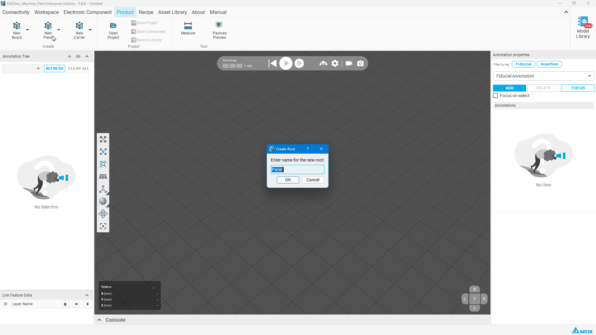
Figure P02-01: Create a Panel
Step 02 | Import the standard Board
Right-click the Panel root node and select Import Board ; set Group to ProductCatalog, select Demo_Single_Board , then select OK.
Check after the operation: The source Board appears in the Panel.
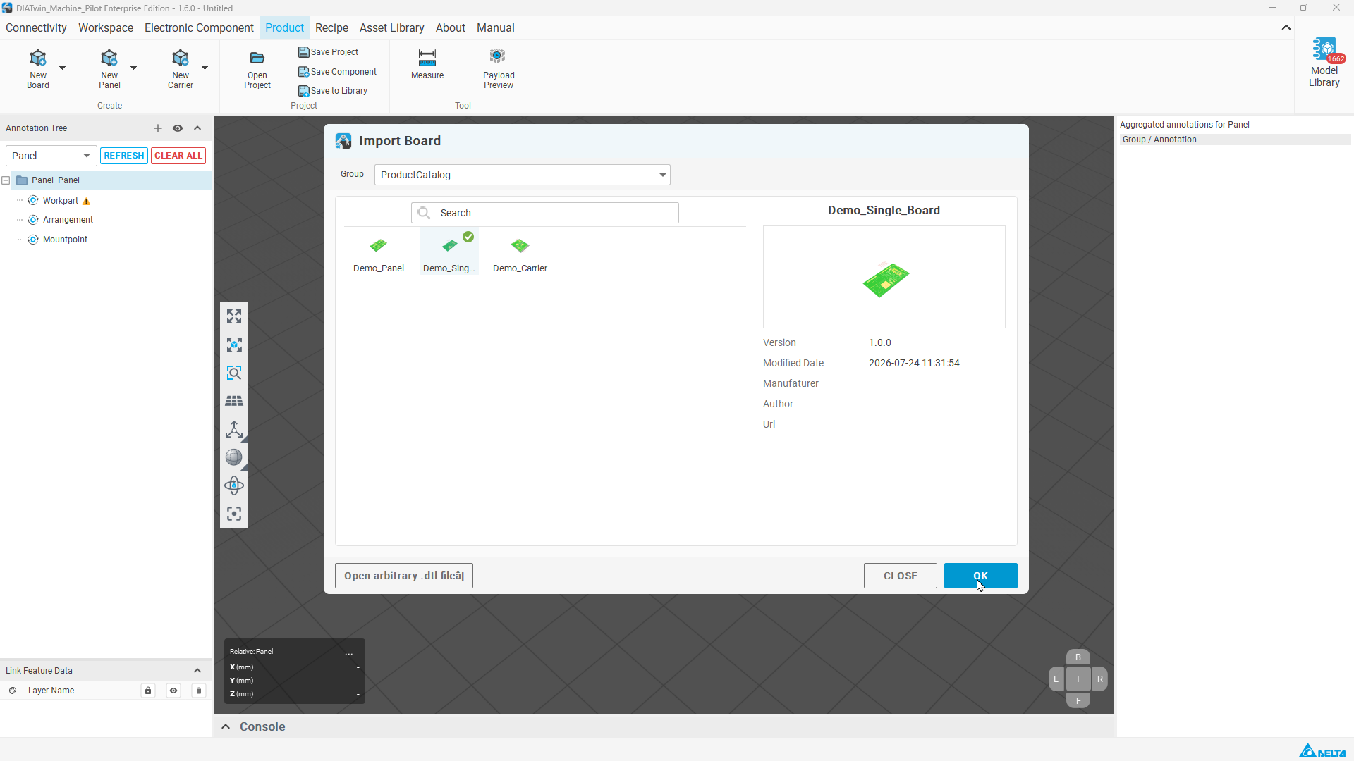
Figure P02-02: Import the standard Board
Step 03 | Set the arrangement
At the Panel level, select Arrangement , and in Simple Arrangement confirm Source Node is Demo_Single_Board. Select Grid. Enter 2 and 1 in the two count fields from top to bottom; set Offset X=0 mm, Offset Y=180 mm, and Offset Rot=0°.
Check after the operation: The bottom preview shows two instances (2 × 1).
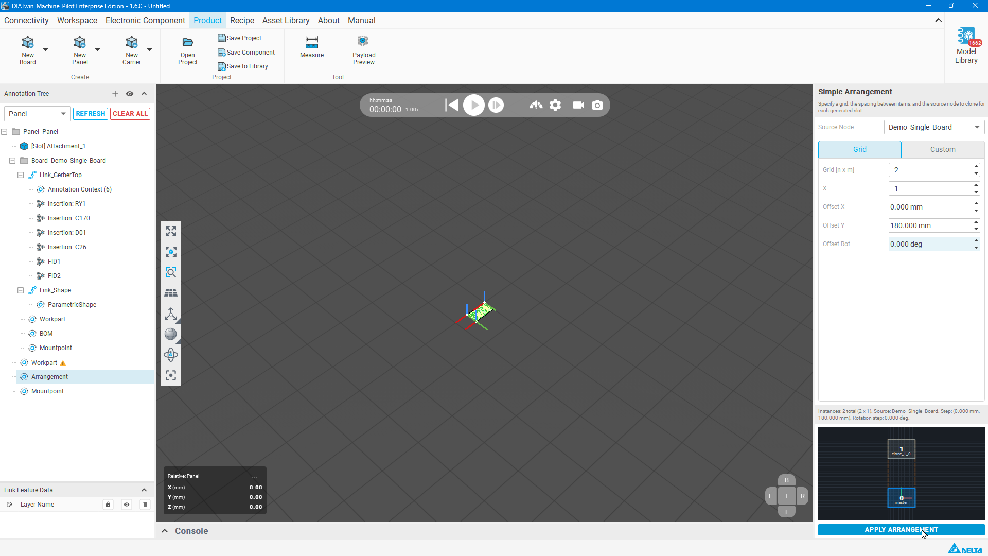
Figure P02-03: Set the arrangement
Step 04 | Apply the arrangement
Select APPLY ARRANGEMENT and inspect the added boards and 3D arrangement.
Check after the operation: Two child boards can be identified.
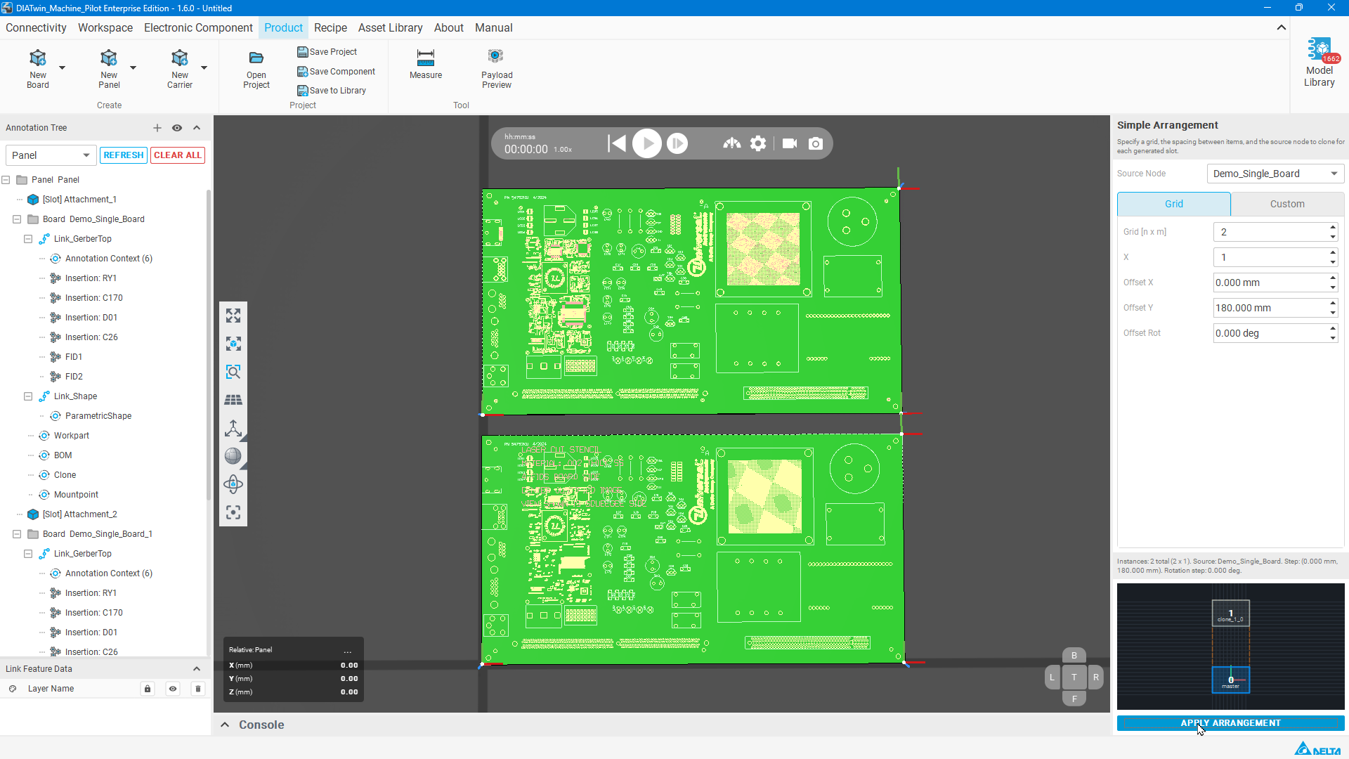
Figure P02-04: Apply the arrangement
Step 05 | Create the frame
Right-click the Panel root node and select Create PanelFrame.
Check after the operation: Panel Frame is added to the tree.
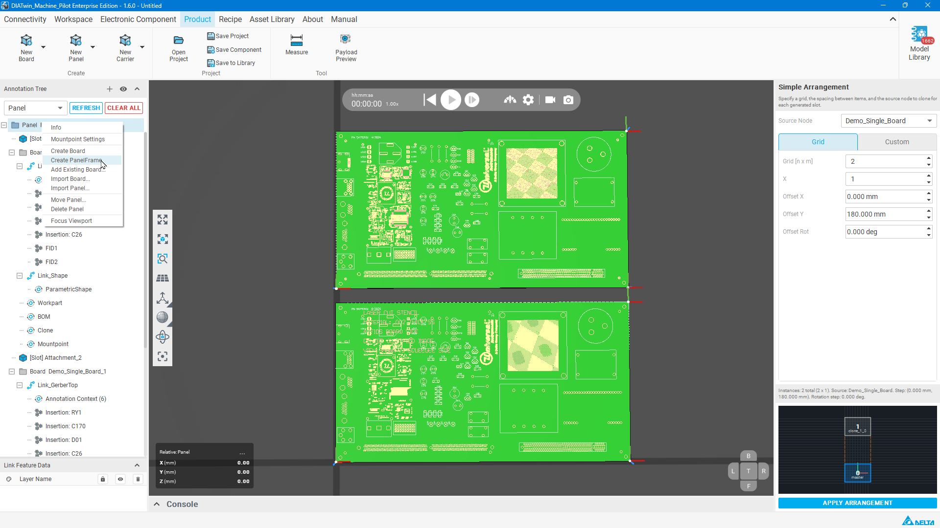
Figure P02-05: Create the frame
Step 06 | Generate the frame
Select Panel Frame, set the frame color, enter Length=350, Width=380, and Height=3 mm, then select GENERATE.
Check after the operation: The panel frame appears in the 3D view.
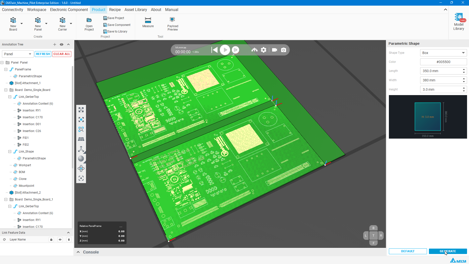
Figure P02-06: Generate the frame
Step 07 | Adjust the frame position
Right-click Panel Frame and choose Move Link . Use Offset, enter X=-10, Y=-10, and Z=-0.1, then select OK.
Check after the operation: The frame position changes according to the settings.
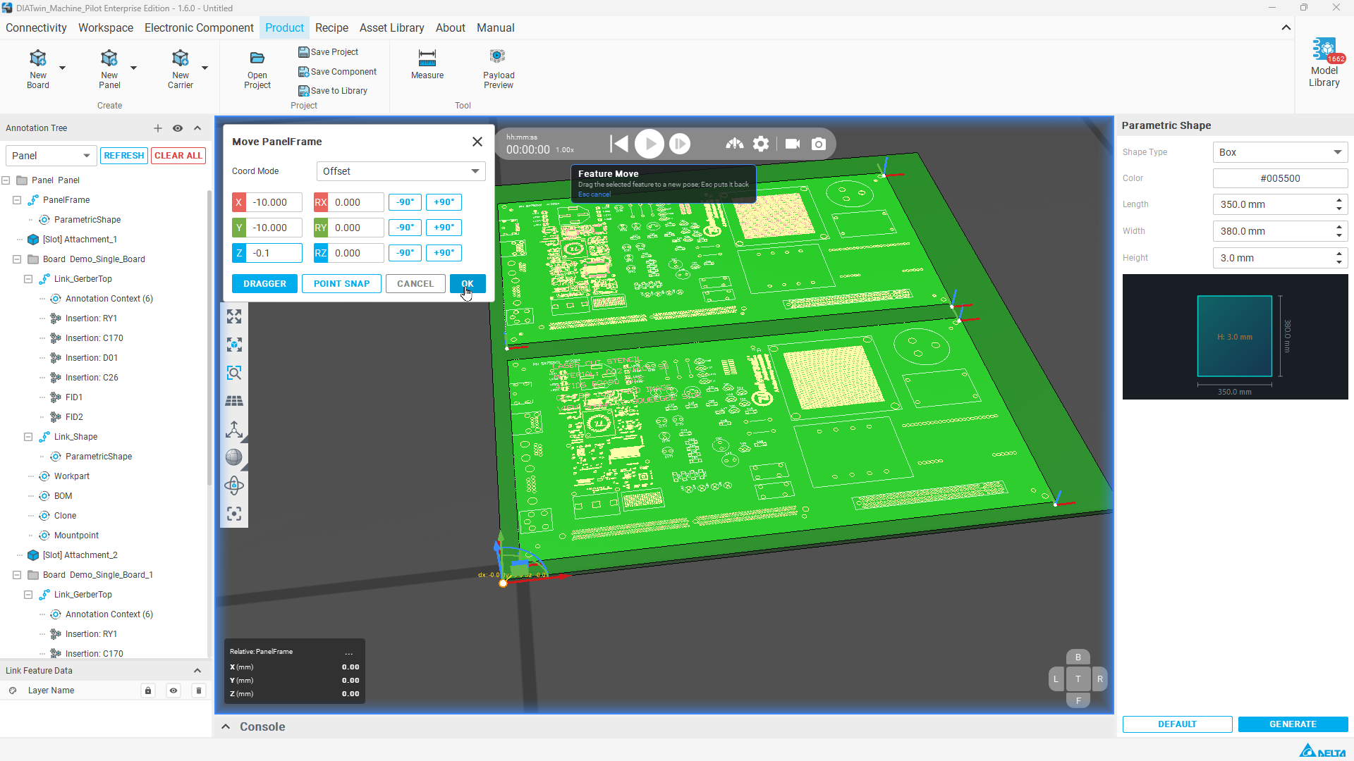
Figure P02-07: Adjust the frame position
Step 08 | Set Workpart dimensions
Select Workpart at the Panel level, then on the right select Measure Diagonal ; first pick the lower-right corner of the bottom face, then the diagonally opposite upper-left corner of the top face. Return to Workpart and check Width, Length, and Thickness. Measure Diagonal is expected to measure and populate thickness automatically; Thickness may also be entered manually.
Check after the operation: This example uses Width=380, Length=350, and Thickness=3 mm for the whole panel.
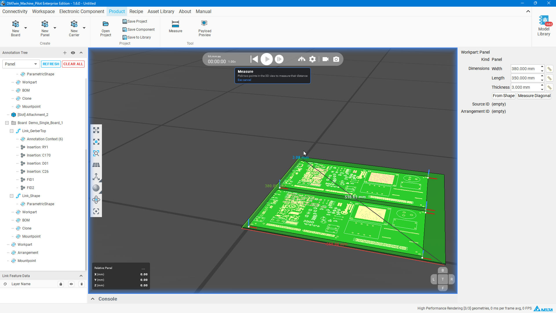
Figure P02-08: Set Workpart dimensions
Step 09 | Create the default locating point
Right-click the Panel's Mountpoint node and select Create Mount Point , then select Corner Mount Point to view the default work coordinate system.
Check after the operation: Corner Mount Point and its locating marker are visible.
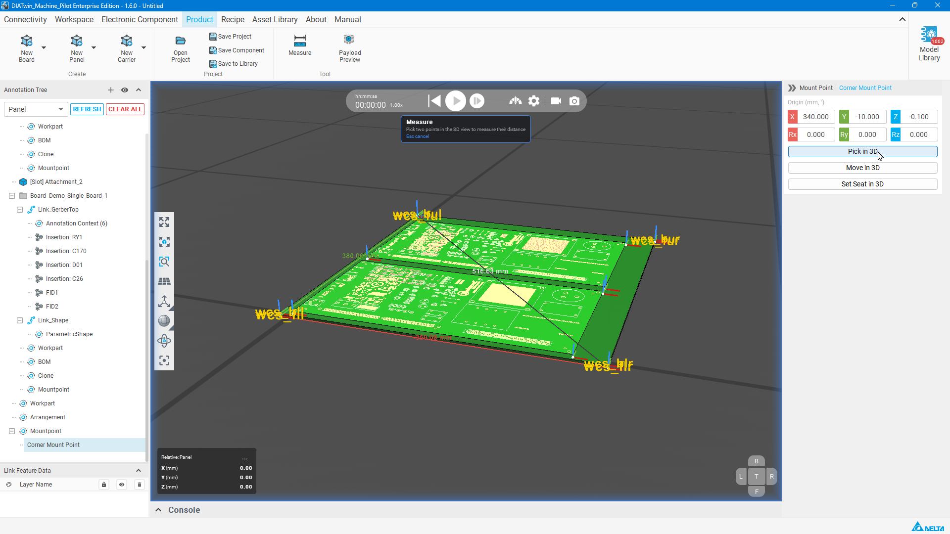
Figure P02-09: Create the default locating point
Step 10 | Save the panel
Select Save to Library . In Save to Asset Library, check Name, Save folder, and ProductCatalog in Group membership. Use Capture from 3D view to update Preview, then select OK.
Check after the operation: A save-success message appears; the example is Panel_1.
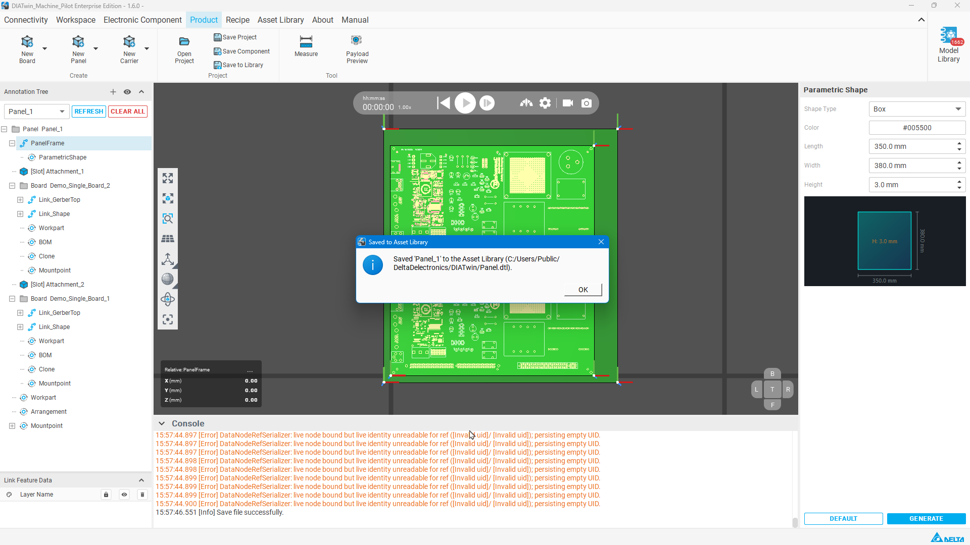
Figure P02-10: Save the panel
Step 11 | Find the product in Recipe
Select Recipe , then in Project Creation open Create Project and find the saved product in the Product list.
Check after the operation: Find the product by the name you saved. Panel_1 and Panel are names used in this example.
Completion checks
- [ ] The arrangement count matches the settings.
- [ ] The frame, Workpart, and default locating point are complete.
- [ ] Saving succeeded and your product can be found in Recipe.
Limitations and notes
Choose and record a product name when saving, then select that name in Recipe. After selecting the product, complete mounting and configuration for the machine.