 DIATwin
P03 | Create a Concept Carrier
Purpose and expected result
Create a concept carrier with two identical Demo_Single_Board boards. Use a Box for its shape, set product positions, dimensions, and the default locating point, then save and find it in Recipe.
Before you start
Demo_Single_Board must be in ProductCatalog. This task uses two identical PCBs, not two different products.
Example values and adjustable items
| Item | Example value | Adjustment principle |
|---|---|---|
| Name | Carrier | May be customized |
| Planar offset of the second board | Offset X=330, Y=340 mm, RZ=180° | Example setting |
| Height of both boards | Absolute Z=10.1 mm | Retain existing X/Y and rotation |
| Box Length/Width/Height | 360/370/10 mm | Adjust to the arrangement envelope |
| Carrier shape position | Offset X=-15, Y=-15, Z=0 mm | Example setting |
Procedure
Step 01 | Create a Carrier
Select Product → New Carrier. In Create Root, enter Carrier , then select OK.
Check after the operation: The Carrier root node appears.
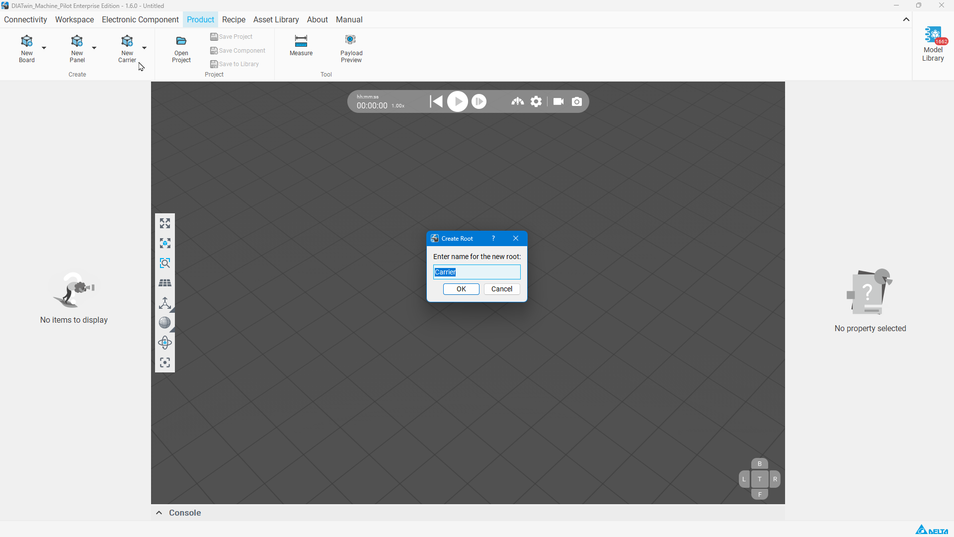
Figure P03-01: Create a Carrier
Step 02 | Load the first Board
Right-click the Carrier root → Open Project.... Select Demo_Single_Board in ProductCatalog and select OK.
Check after the operation: The first Board appears inside Carrier.
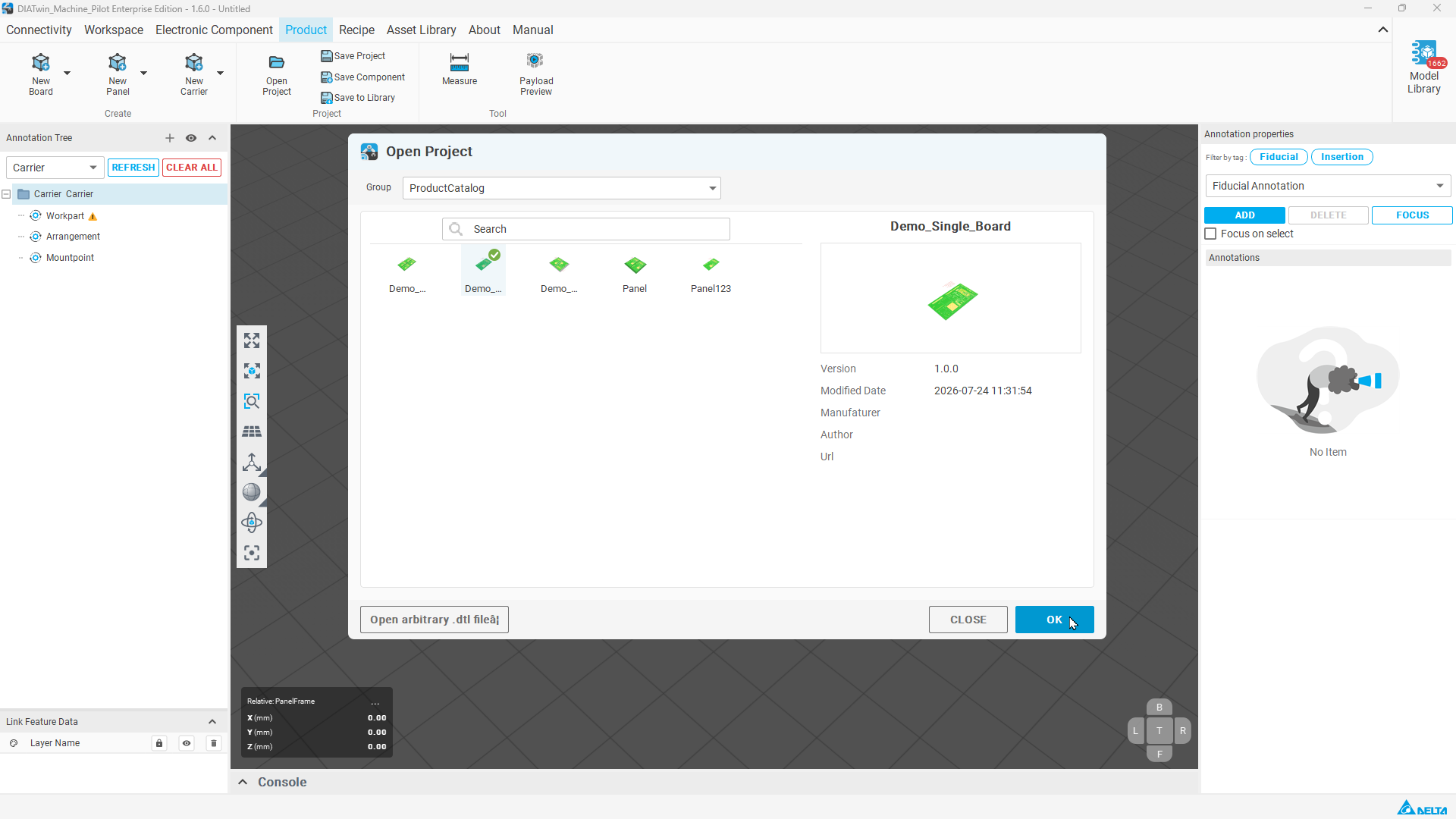
Figure P03-02: Load the first Board
Step 03 | Load the second Board
Repeat root-node right-click → Open Project..., select Demo_Single_Board again, and select OK. Expand Carrier and check Demo_Single_Board and Demo_Single_Board_1.
Check after the operation: Both Board nodes are present, even if their 3D shapes overlap temporarily.
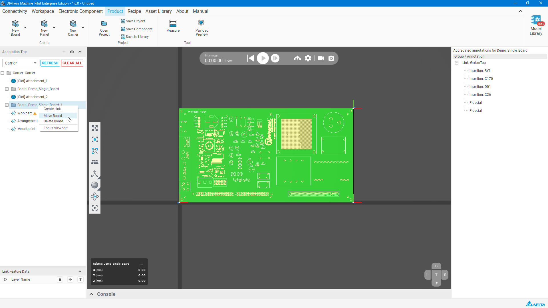
Figure P03-03: Load the second Board
Step 04 | Focus on the objects
Right-click the Carrier root → Focus Viewport.
Check after the operation: The view includes the objects currently inside the carrier.
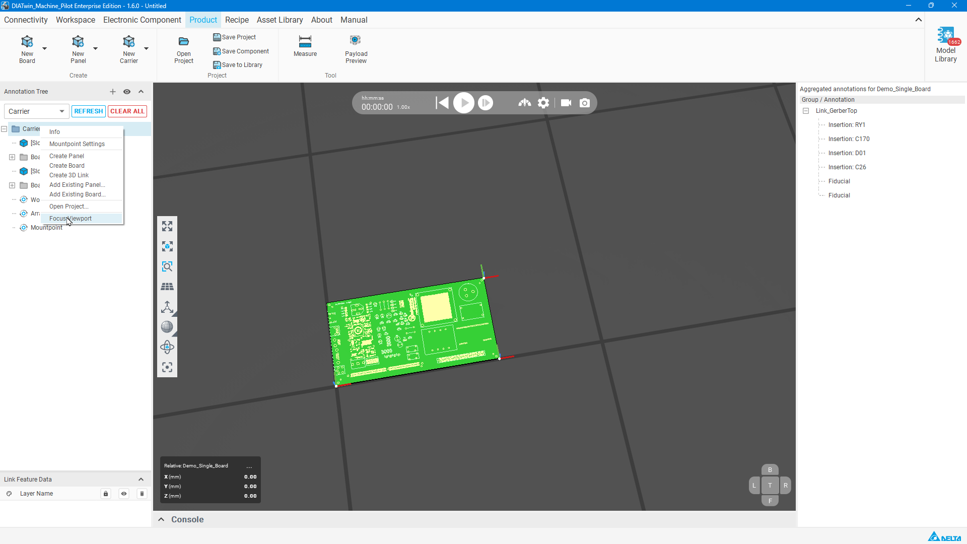
Figure P03-04: Focus on the objects
Step 05 | Position the second board
Right-click Demo_Single_Board_1 → Move Board.... Select Offset for Coord Mode. Enter X=330, Y=340, Z=0 mm, RX=0, RY=0, and RZ=180°, then select OK.
Check after the operation: The second board is offset and rotated 180°.
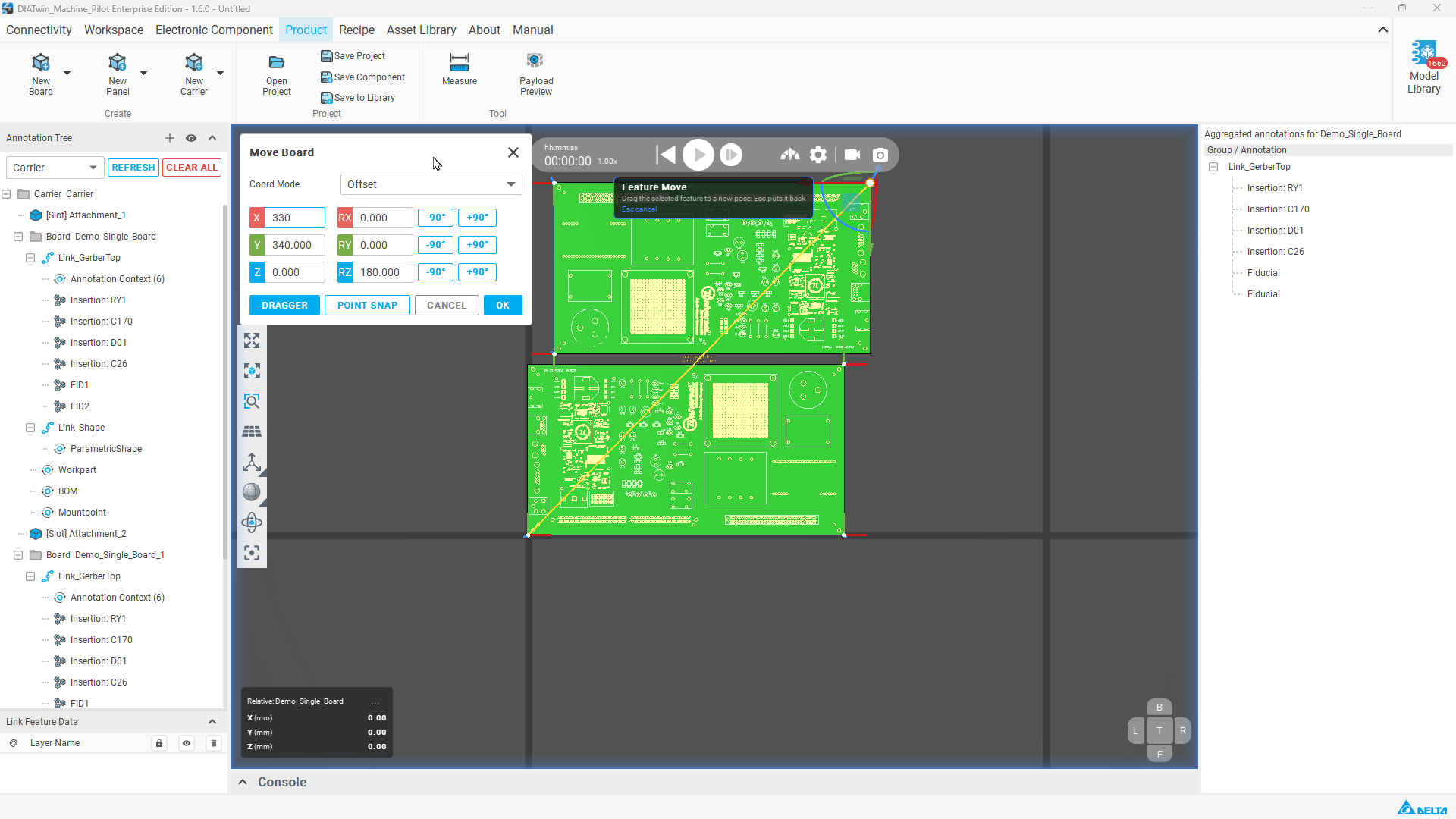
Figure P03-05: Position the second board
Step 06 | Create the concept shape
Right-click the Carrier root → Create 3D Link. Select ParametricShape under its Link_Shape and confirm Shape Type=Box.
Check after the operation: Parametric Shape properties appear on the right.
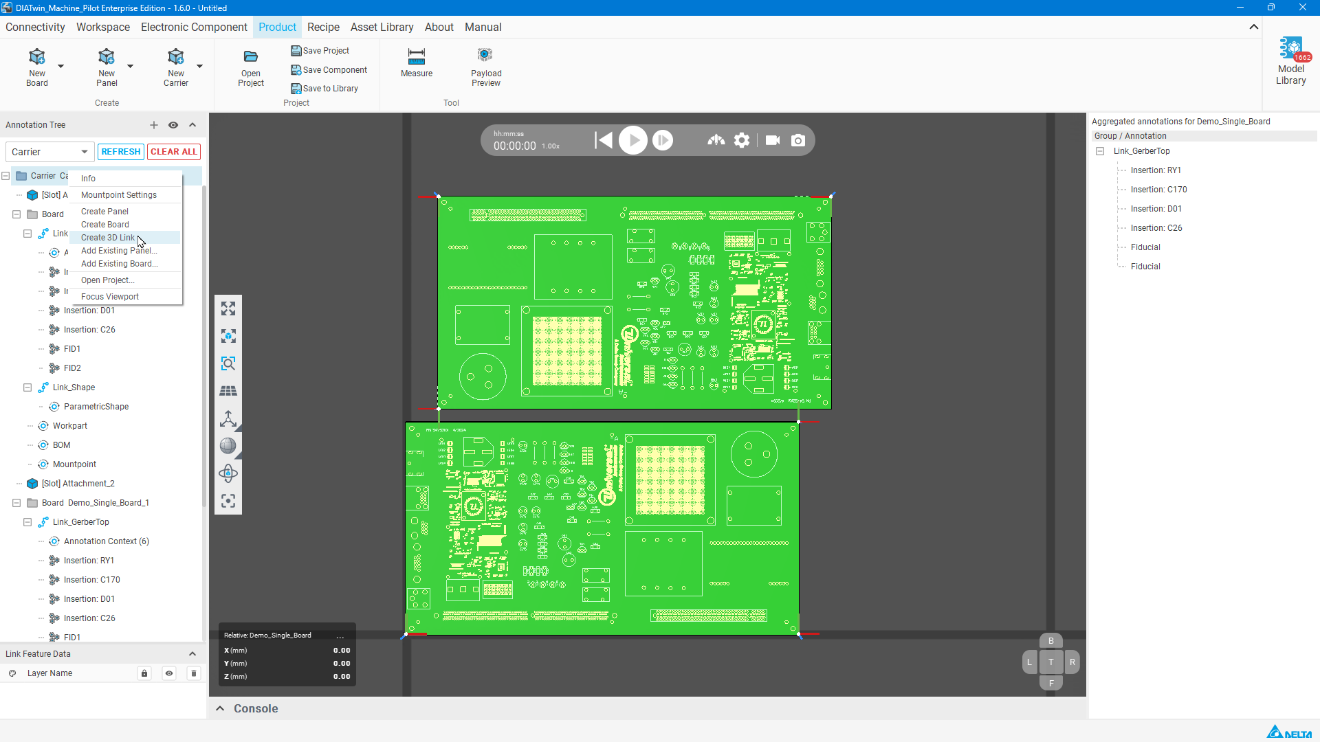
Figure P03-06: Create the concept shape
Step 07 | Measure the arrangement envelope
Select Measure on the toolbar. Pick the lower-left and then upper-right corners of the PCB group to read the arrangement envelope. Exit measurement mode before editing properties.
Check after the operation: The example shows 330 / 340 mm and a diagonal of about 473.81 mm, as a reference for the shape dimensions.
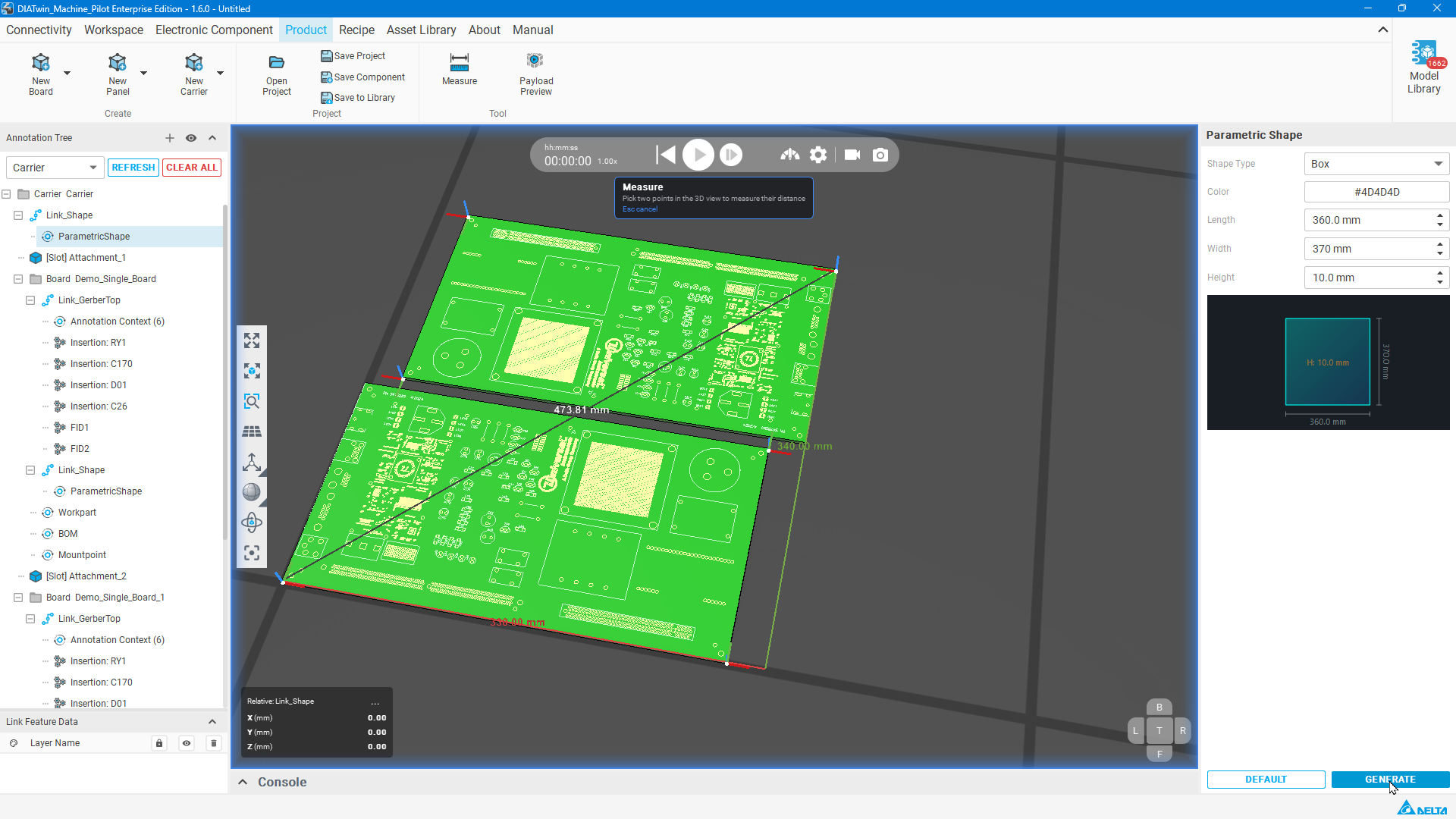
Figure P03-07: Measure the arrangement envelope
Step 08 | Generate the carrier Box
In Parametric Shape, set the color (example: #4D4D4D), Length=360, Width=370, and Height=10 mm. Select GENERATE.
Check after the operation: The gray carrier shape is generated.
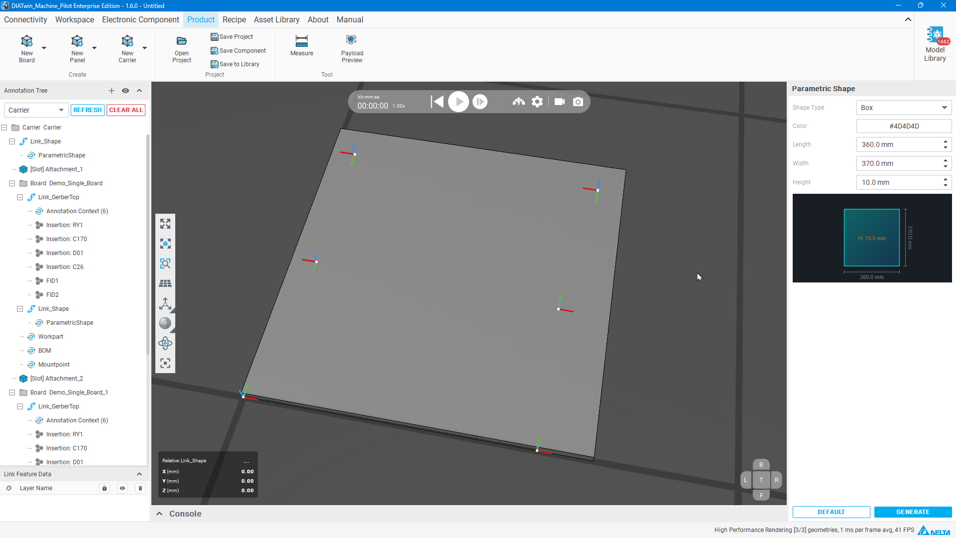
Figure P03-08: Generate the carrier Box
Step 09 | Adjust both board heights
For each Board node, right-click → Move Board.... Switch to Absolute and set Z=10.1 mm. Keep each board's X/Y and rotation, then select OK.
Check after the operation: Both boards are above the carrier. Z is an absolute coordinate, not an additional 10.1 mm offset.
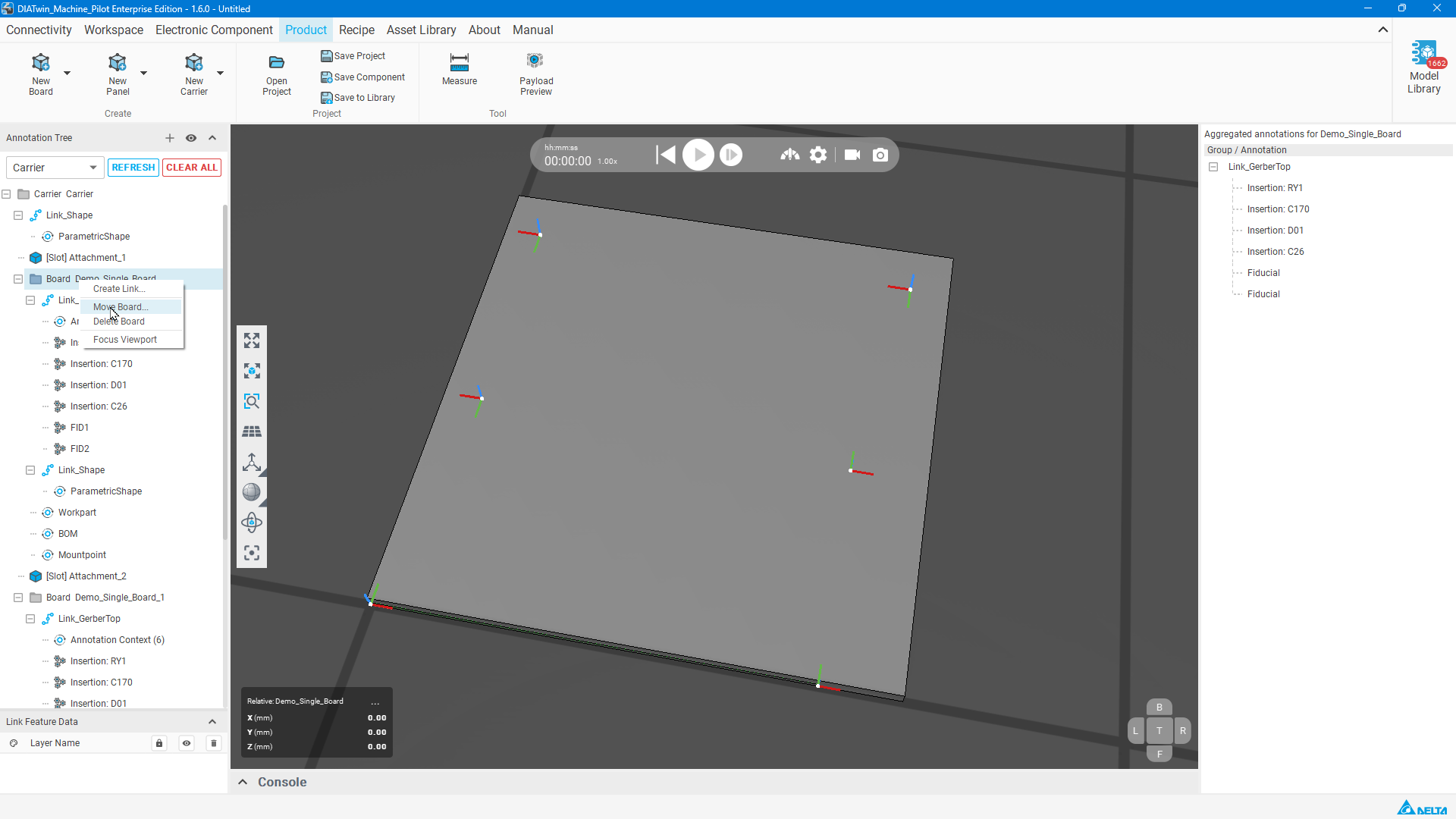
Figure P03-09: Adjust both board heights
Step 10 | Move the carrier shape
Select Link_Shape at Carrier level, right-click, and select Move Link to open Move Link_Shape. Use Offset; enter X=-15, Y=-15, Z=0, keep rotation at 0, and select OK.
Check after the operation: The gray carrier and two boards match the example arrangement.
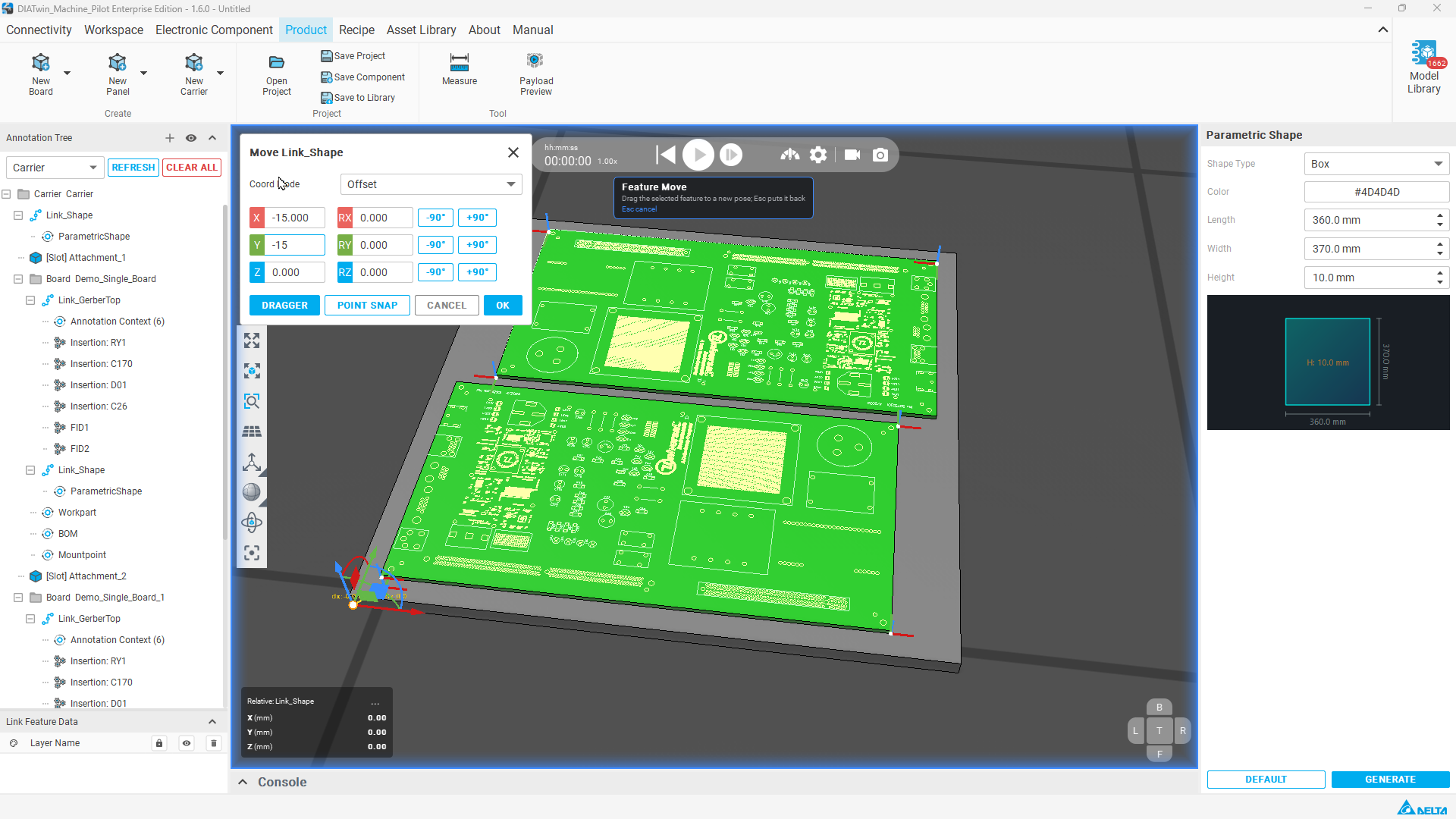
Figure P03-10: Move the carrier shape
Step 11 | Set Workpart
Select Workpart at Carrier level, not inside a Board. Select Measure Diagonal; pick the lower-right corner of the carrier's bottom face, then the diagonally opposite upper-left corner of its top face. Check Width, Length, and Thickness in properties.
Check after the operation: Verify Width=370, Length=360, and Thickness=10 mm for this example. Use Measure Diagonal to measure thickness, or enter it manually.
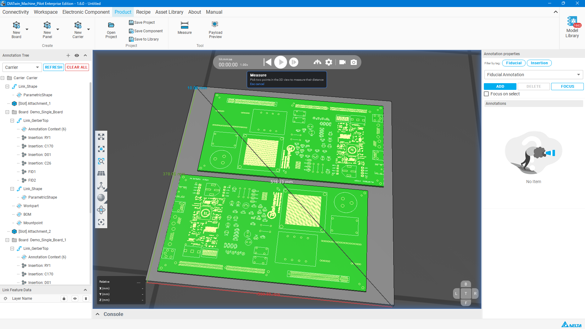
Figure P03-11: Carrier geometry measurement: length 360, width 370, height 10 mm
Step 12 | Create the default locating point
Right-click Carrier's Mountpoint → Create Mount Point, then select Corner Mount Point.
Check after the operation: The default corner point is displayed; no additional manual point picking is needed.
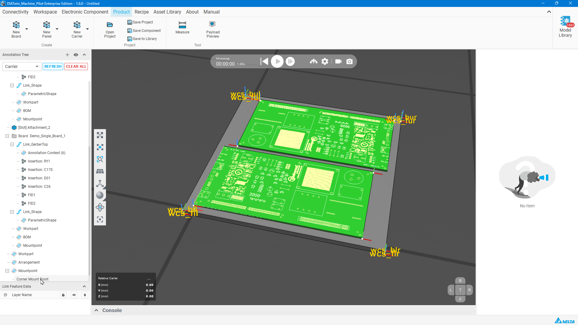
Figure P03-12: Create the default locating point
Step 13 | Save Carrier
Select Save to Library. Check Name=Carrier (or your name), the destination path, and ProductCatalog in Group membership. Select Capture from 3D view, check the preview, then select OK.
Check after the operation: Saved Carrier to the Asset Library appears. Select OK to close it.
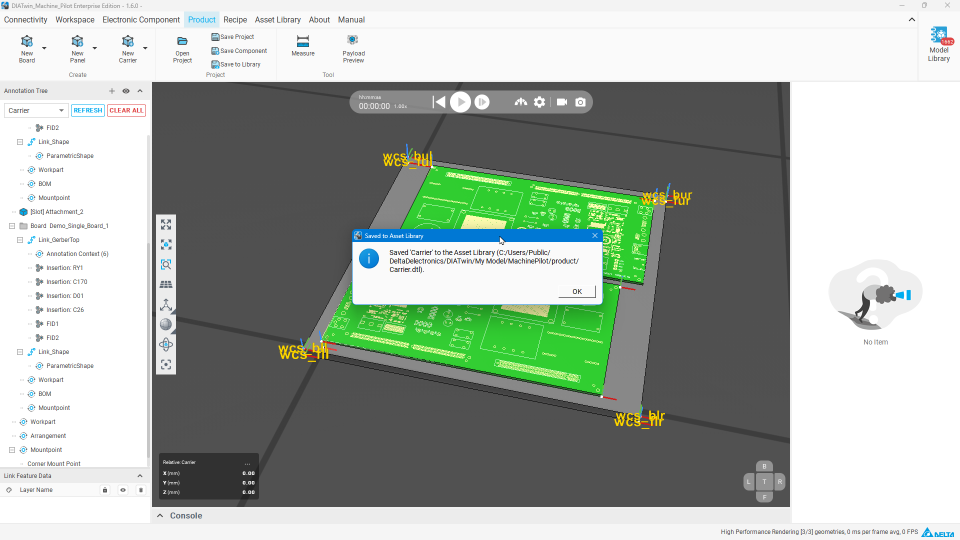
Figure P03-13: Save Carrier
Step 14 | Find the product in Recipe
Select Recipe → Project Creation → Create Project and find your saved Carrier in the Product list.
Check after the operation: Your carrier can be identified and selected.
Completion checks
- [ ] Carrier contains two identical Demo_Single_Board boards.
- [ ] The second board's rotation and arrangement are correct; both boards have Z=10.1.
- [ ] The concept shape, dimensions, and default locating point are set.
- [ ] The saved result can be found in Recipe.
Limitations and notes
The box shape supports carrier-layout planning; it is not a manufacturing-ready fixture. Check collisions and manufacturability before use. Set board heights using the values in this lesson.