 DIATwin
P04 | Create a Production Carrier from a STEP Model
Purpose and expected result
Create an independent Carrier, import the production STEP shape, and position two PCBs. Set dimensions, locating points, and save information, then find the carrier in Recipe.
Before you start
Select Product → New Carrier, enter a name, and select OK. Right-click the Carrier root → Open Project..., select Demo_Single_Board in ProductCatalog, and select OK. Repeat to load a second identical Board. Right-click the Carrier root → Create 3D Link. This is a new project; do not reuse P03's Box, Offset, or Z=10.1. Prepare the training file pcb_holder.stp.
Example values and adjustable items
| Item | Example value | Adjustment principle |
|---|---|---|
| Saved name | Carrier_Stp | May be customized |
| STEP | Tutorials data/cad/pcb_holder.stp | Use the actual installation location |
| Carrier position | Absolute X=155, Y=170, Z=0 mm | Example value |
| Second Board | Absolute X=305, Y=340, Z=0 mm, RZ=180° | Example value |
| Height of both Boards | Z=0 | Do not use the concept-carrier value |
| Workpart Width/Length/Thickness | 436/388/17 mm | Matches the production carrier in this example |
Procedure
Step 01 | Import the STEP shape
Right-click the carrier's Link_Shape and select Import Shape from File.
Check after the operation: The file-selection window opens.
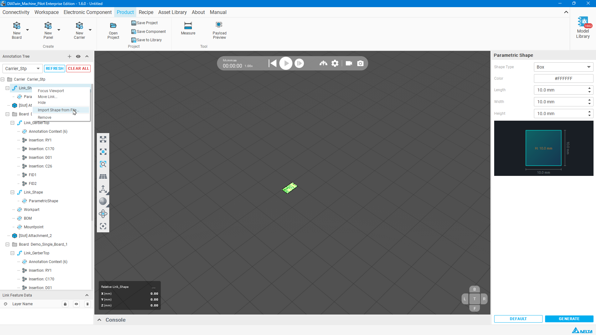
Figure P04-01: Import the STEP shape
Step 02 | Select the training file
Open the cad folder in the training data, select pcb_holder.stp and open it. Reference path shown: C:/Users/Public/DeltaElectronics/DIATwin/My Model/Tutorials data/cad/pcb_holder.stp.
Check after the operation: The production carrier shape appears in the 3D view.
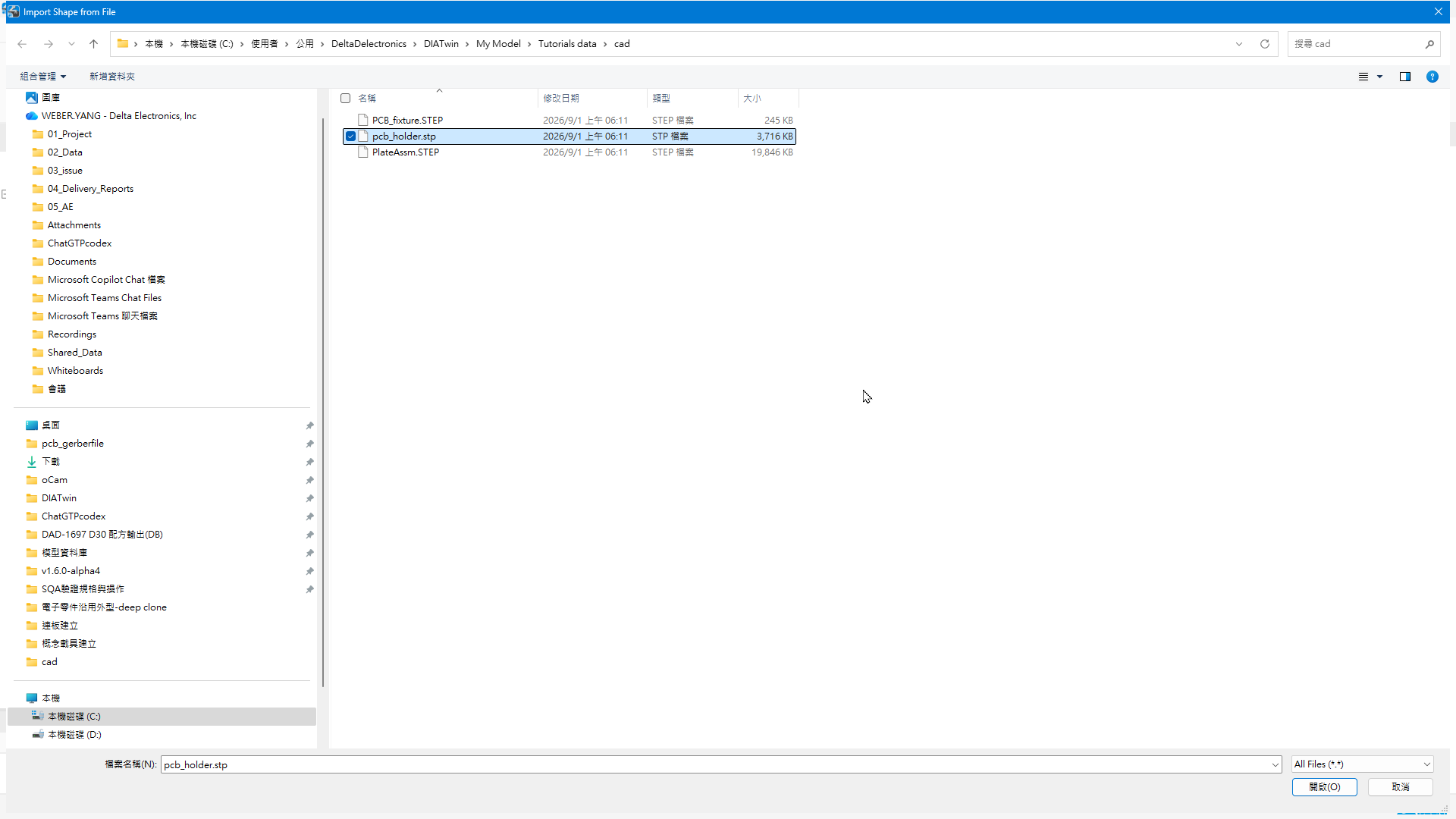
Figure P04-02: Select the training file
Step 03 | Hide the floor
Select Hide Floor in the Display Bar on the left of the 3D Rendering Viewport.
Check after the operation: The floor is hidden, making the carrier and PCBs easier to inspect.
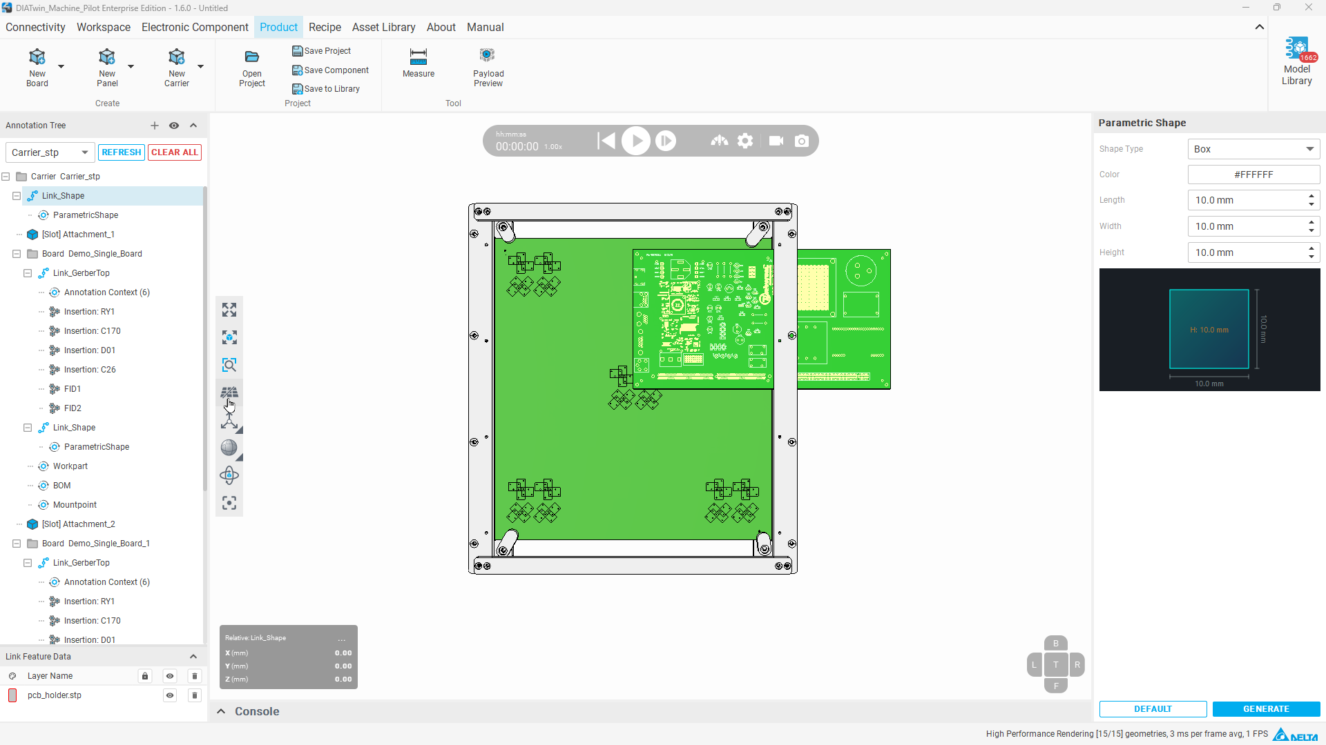
Figure P04-03: Hide the floor
Step 04 | Open carrier movement
Right-click the carrier's Link_Shape, select Move Link, and switch to Absolute.
Check after the operation: Move Link_Shape displays absolute-position fields.
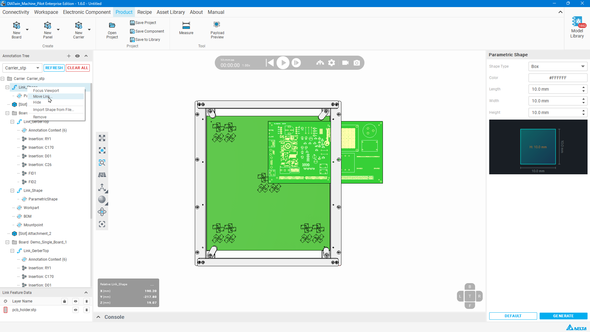
Figure P04-04: Open the carrier geometry movement settings
Step 05 | Set the carrier position
Enter X=155, Y=170, and Z=0 mm; keep RX, RY, and RZ at 0, then select OK.
Check after the operation: The carrier shape moves to the example position.
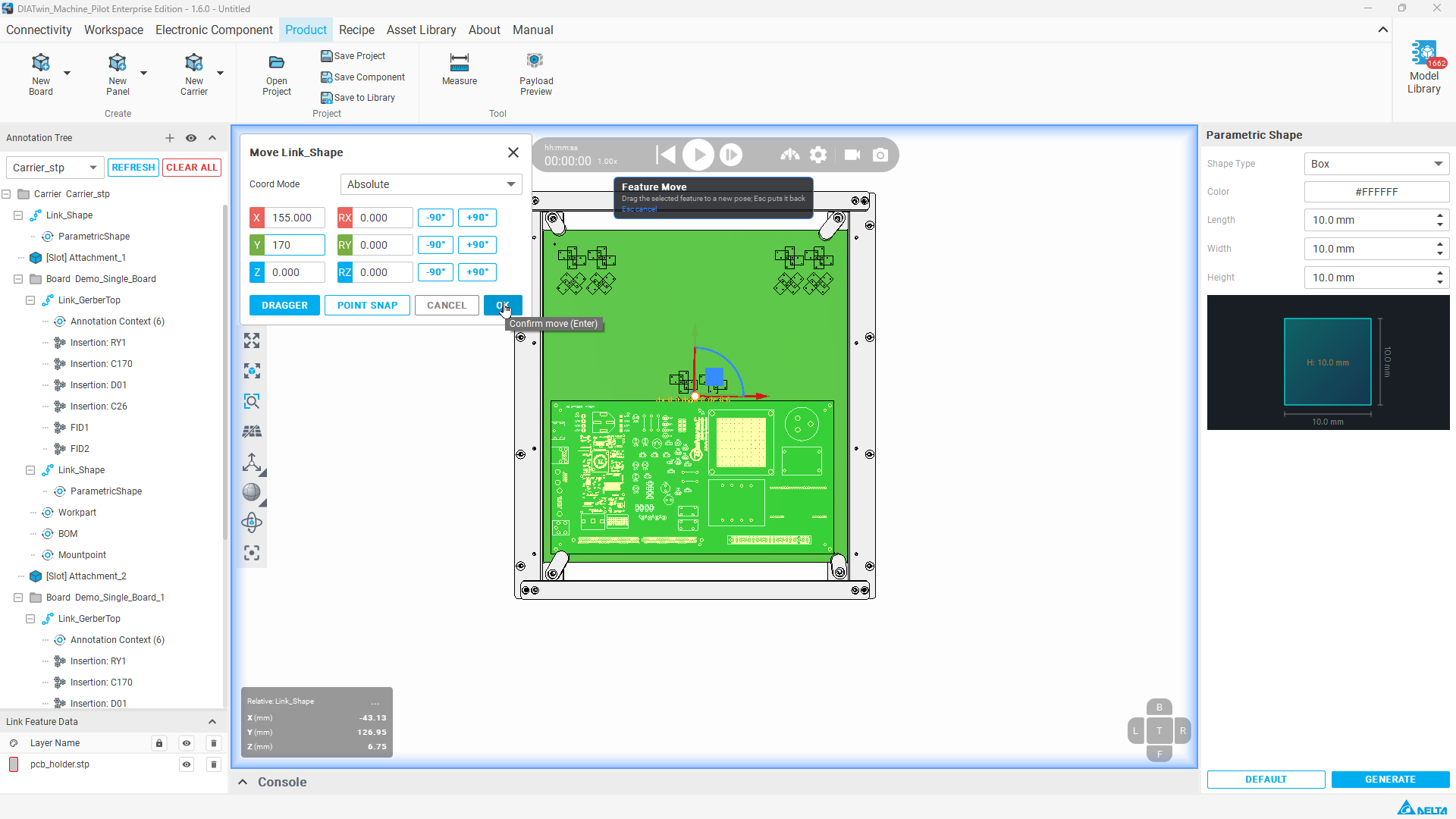
Figure P04-05: Set the carrier position
Step 06 | Set the second Board
Right-click the second Board and select Move Board. Switch to Absolute; enter X=305, Y=340, Z=0, and RZ=180° (keep RX/RY at 0), then select OK. Keep the first Board's Z at 0.
Check after the operation: The second board's offset and orientation match the example.

Figure P04-06: Set the second Board
Step 07 | Select the carrier Workpart
Select Workpart at Carrier level and check the target object on the right.
Check after the operation: The object being edited is the entire Carrier.
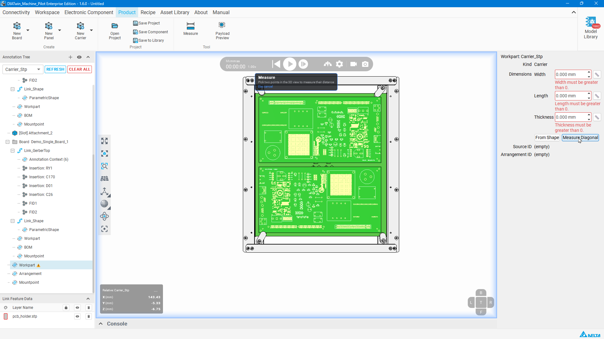
Figure P04-07: Select the carrier Workpart
Step 08 | Measure and set dimensions
Use Measure Diagonal on the right. Pick a bottom-face corner and the diagonally opposite top-face corner to measure the entire production carrier. Dimensions and thickness are expected to populate automatically; Thickness may also be entered manually. Verify Width=436, Length=388, and Thickness=17 mm.
Check after the operation: All three fields match the example values.
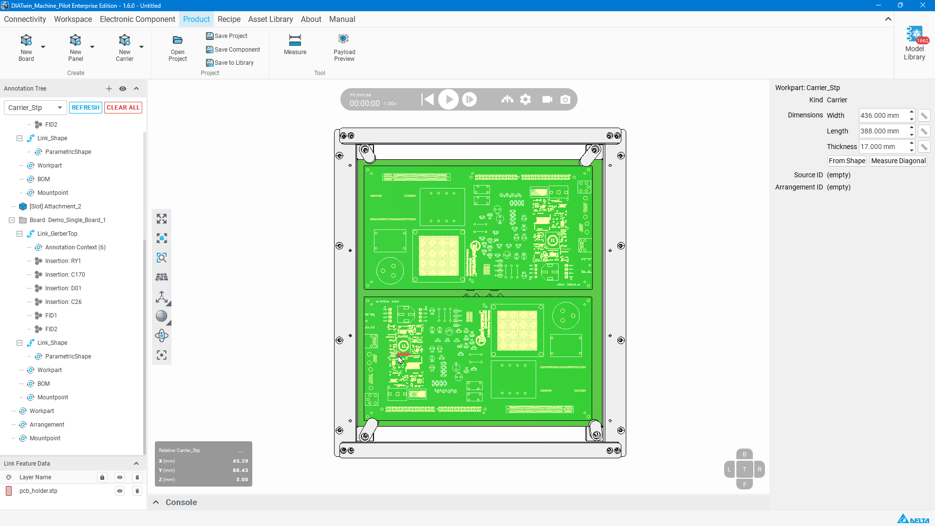
Figure P04-08: Measure and set dimensions
Step 09 | Create a Mount Point
Right-click Carrier's Mountpoint → Create Mount Point. Select Corner Mount Point to preview the default locating point at the carrier's lower-right corner.
Check after the operation: The default locating point is visible; do not open Set Seat in 3D.
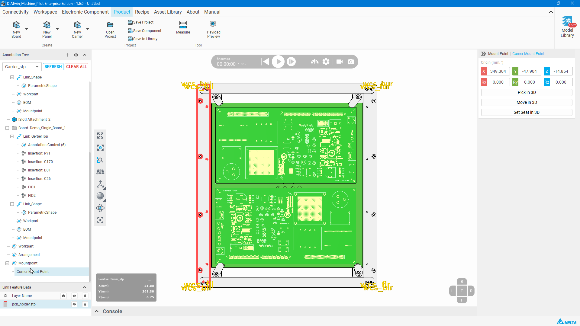
Figure P04-09: Create a Mount Point
Step 10 | Set save information
Select Save to Library. Check Name=Carrier_Stp or your name, Save folder, and the added ProductCatalog group. Select Capture from 3D view, check the carrier preview, then select OK.
Check after the operation: The carrier asset save has been submitted.
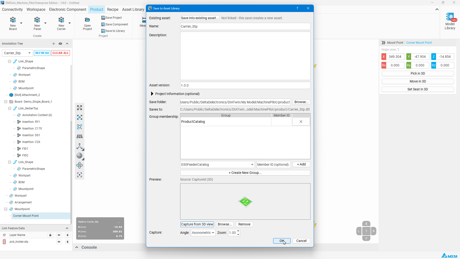
Figure P04-10: Set the product name, save location, and group
Step 11 | Confirm successful saving
Confirm that the asset name in the success message matches the name you saved, then select OK.
Check after the operation: The example message is Saved Carrier_Stp to the Asset Library.
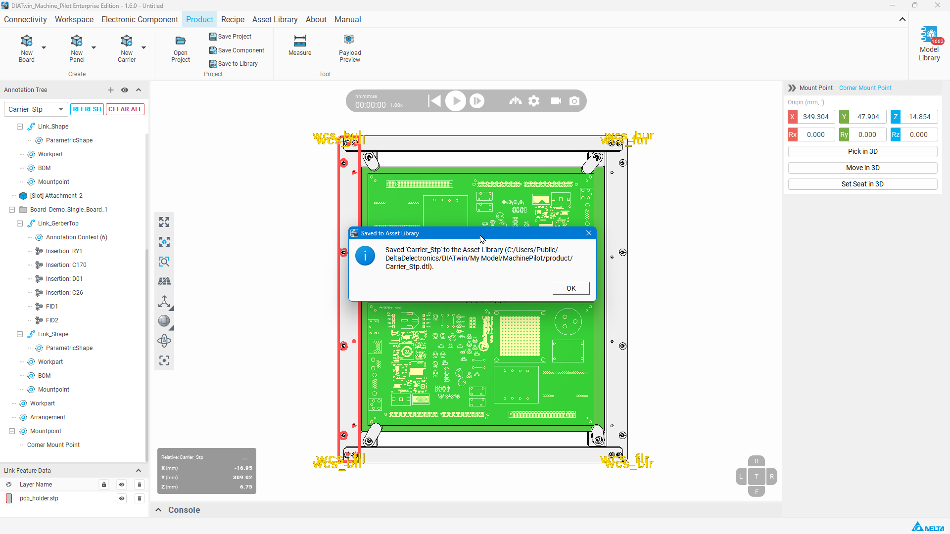
Figure P04-11: Confirm successful saving
Step 12 | Find the product in Recipe
Open Recipe → Project Creation → Create Project. Find Carrier_Stp or your chosen saved name in the Product list.
Check after the operation: The task is complete when the product can be selected.
Completion checks
- [ ] The STEP shape and both boards are loaded.
- [ ] Position, rotation, and dimensions 436 / 388 / 17 match the example settings.
- [ ] The default locating point is created and saving succeeded.
- [ ] The saved product can be found in Recipe.
Limitations and notes
This example creates a carrier from a STEP model. Workpart thickness and Z position are different parameters; check them separately. Verify the physical mounting conditions after saving the product.