 DIATwin
R02 | Auto-Configuration with Reserved Empty Slots
Purpose and expected result
Use Demo_Carrier to practice Lock on empty slots. Keep designated slots empty while the algorithm configures other resources, then import the configuration and complete simulation.
Before you start
Use EmptyInsertionMachine and Demo_Carrier. Feeder and Tool slots to be locked must be empty when you start; Lock retains their current state.
Example values and adjustable items
| Item | Example value | Adjustment principle |
|---|---|---|
| Product | Demo_Carrier | Confirmed starting product for this course |
| Conveyor width | 380mm | Example value |
| Lock empty slots | Feeder17–32, Tool1–4 | Follow this training example; the range may later be changed as needed. |
| Completed result | Record your own Cycle Time | Reproducing 12.840 seconds is not required. |
Procedure
Step 01 | Select the machine and product
Open Recipe → Project Creation → Create Project. Select the empty machine and Demo_Carrier, then NEXT.
Check after the operation: Product Assembly shows Demo_Carrier.
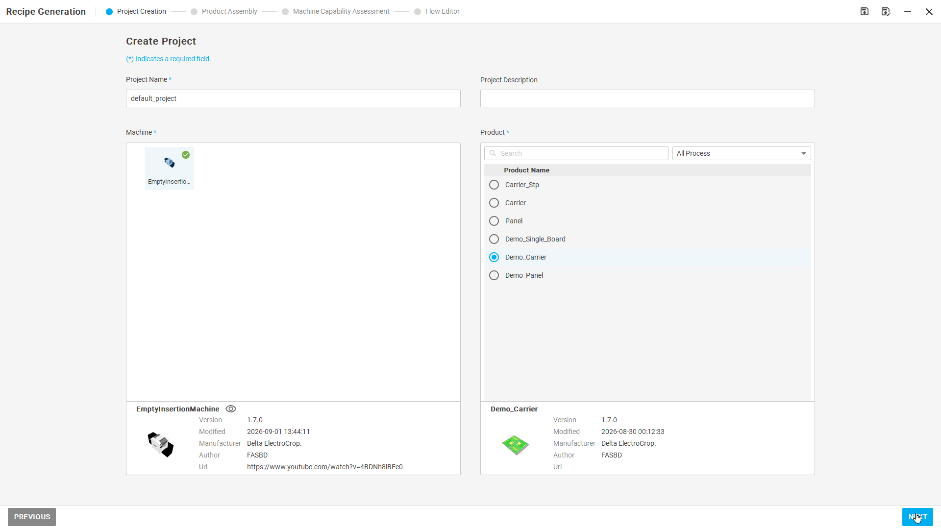
Figure R02-01: Select the machine and product
Step 02 | Confirm product assembly
Check the defaults in Select Position, Adjust Orientation, and Select Attachment Point. Set Adjust Conveyor Width to 380 mm, select CONFIRM, then NEXT.
Check after the operation: Machine Capability Assessment opens.
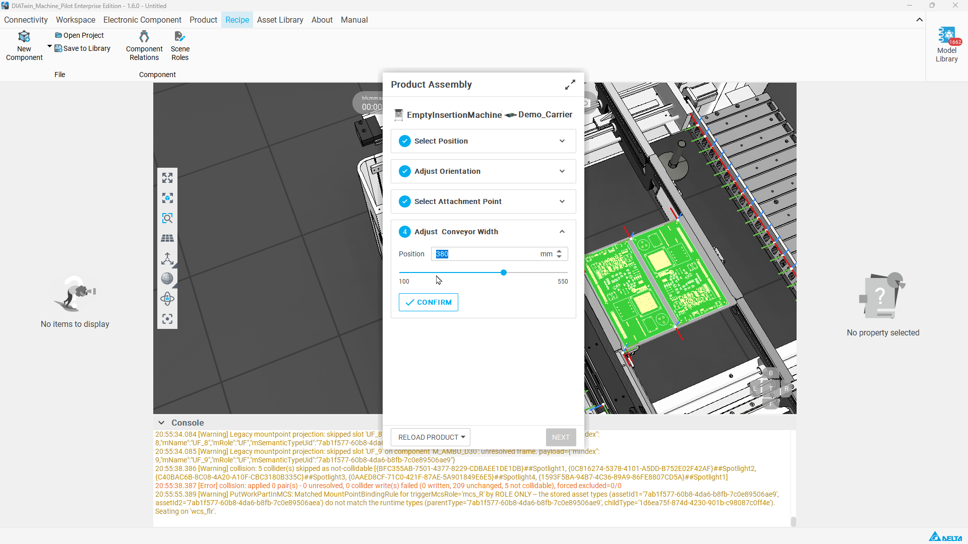
Figure R02-02: Confirm product assembly
Step 03 | Find the slots to keep empty
Switch to Slot → Feeder and scroll to 17–32. Check that Feeder and Part No. are empty.
Check after the operation: The target slots are empty, not slots with installed accessories.
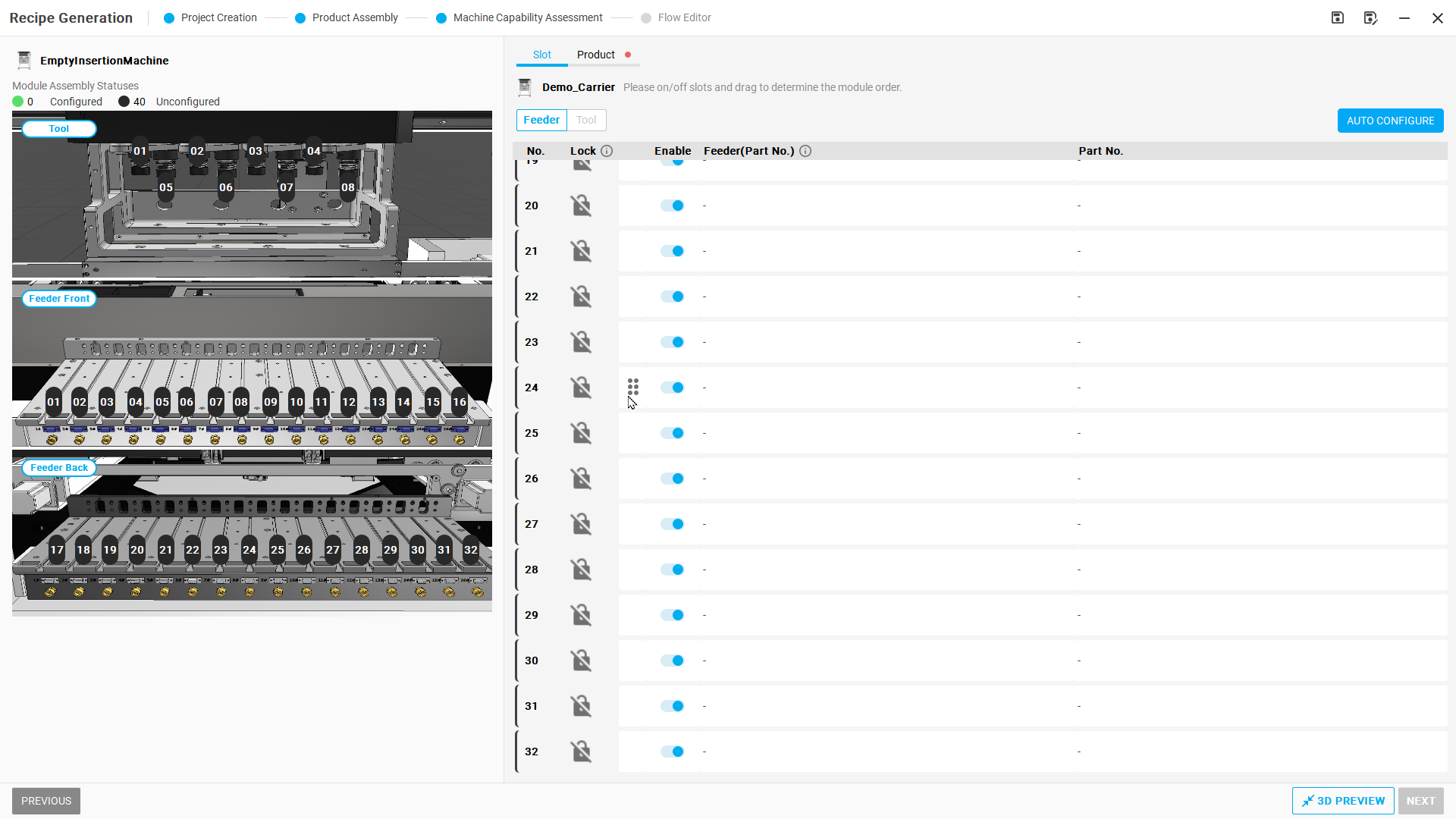
Figure R02-03: Find the slots to keep empty
Step 04 | Lock empty Feeder slots
Enable Lock individually for slots 17–32. Leave 1–16 available to the algorithm.
Check after the operation: The designated slots remain empty with Lock enabled.
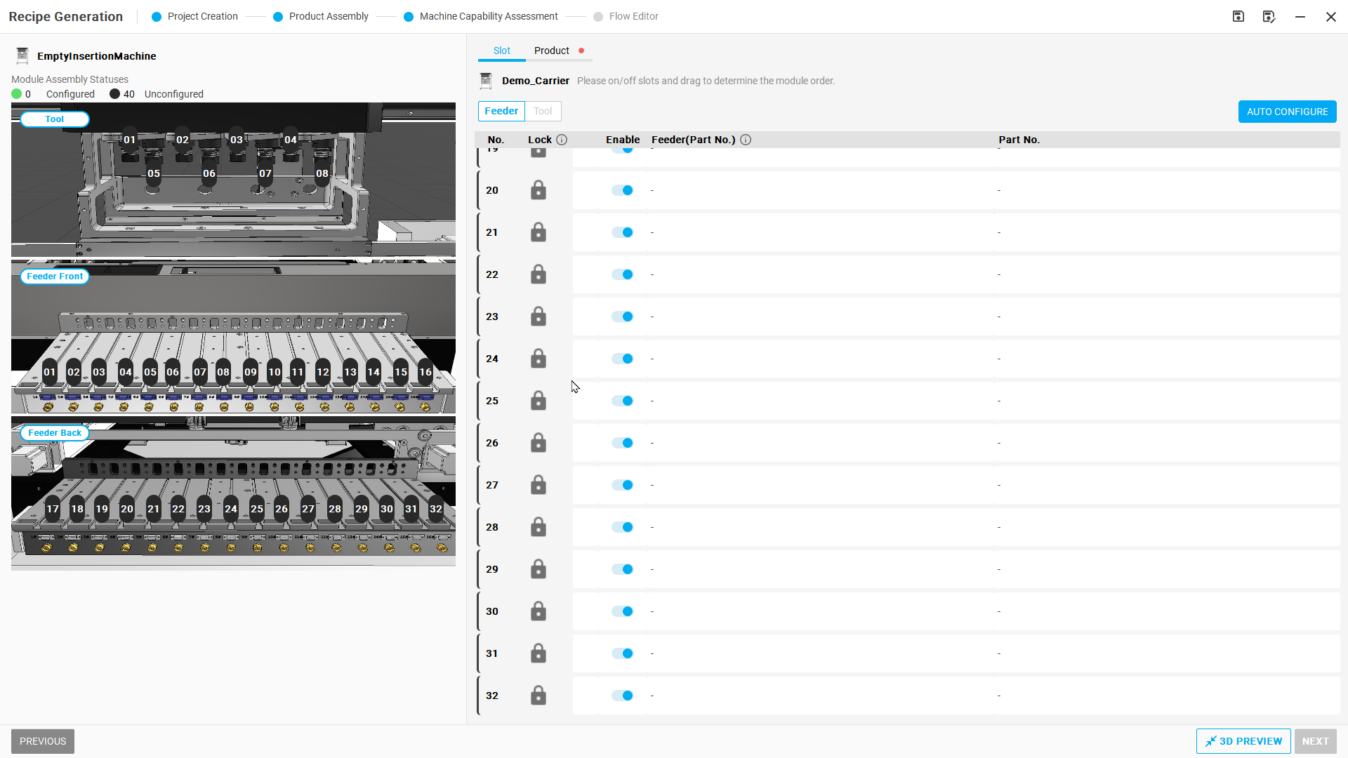
Figure R02-04: Lock empty Feeder slots
Step 05 | Lock empty Tool slots
Switch to Tool, confirm slots 1–4 are empty, then enable Lock for them. Slots 5–8 remain available to the algorithm.
Check after the operation: Tool-slot constraints match this example.
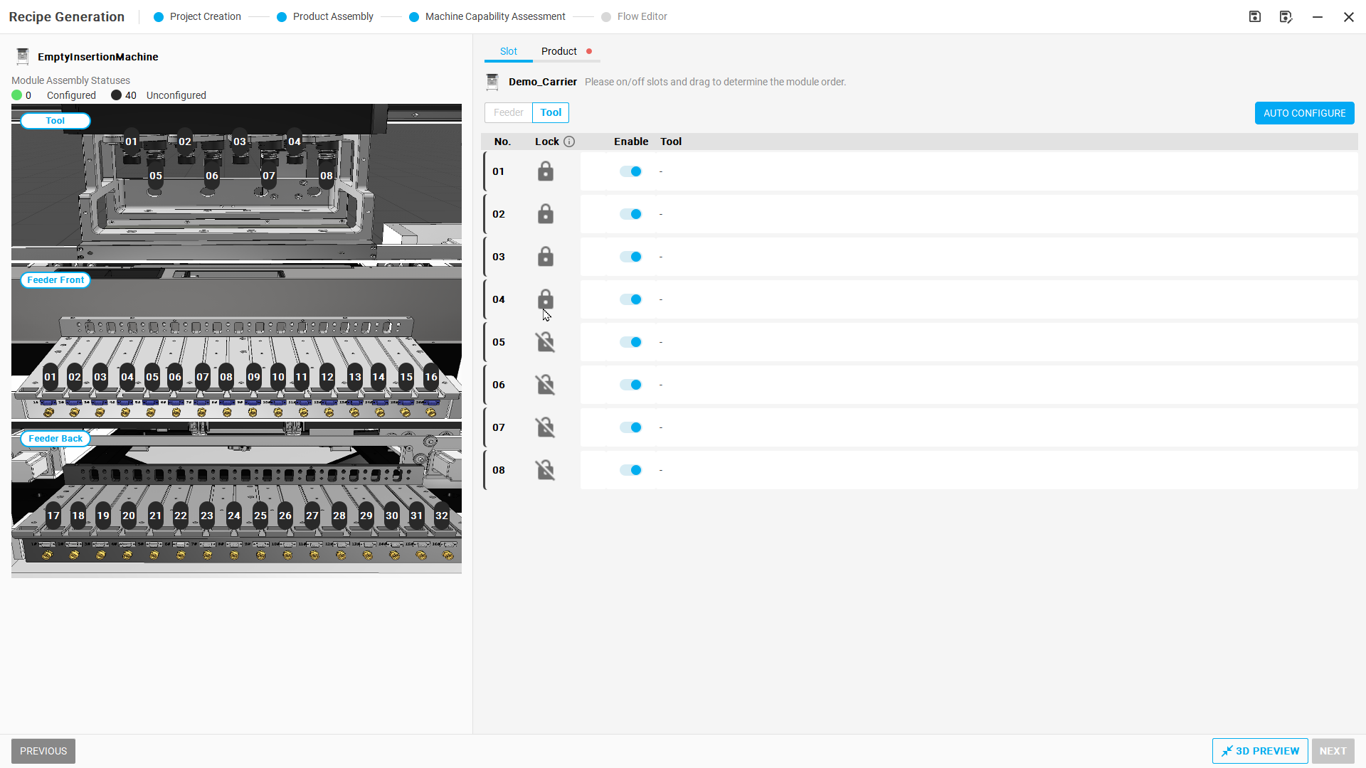
Figure R02-05: Lock empty Tool slots
Step 06 | Start automatic configuration
Select AUTO CONFIGURE and wait for computation to finish.
Check after the operation: Auto Configure Result appears.
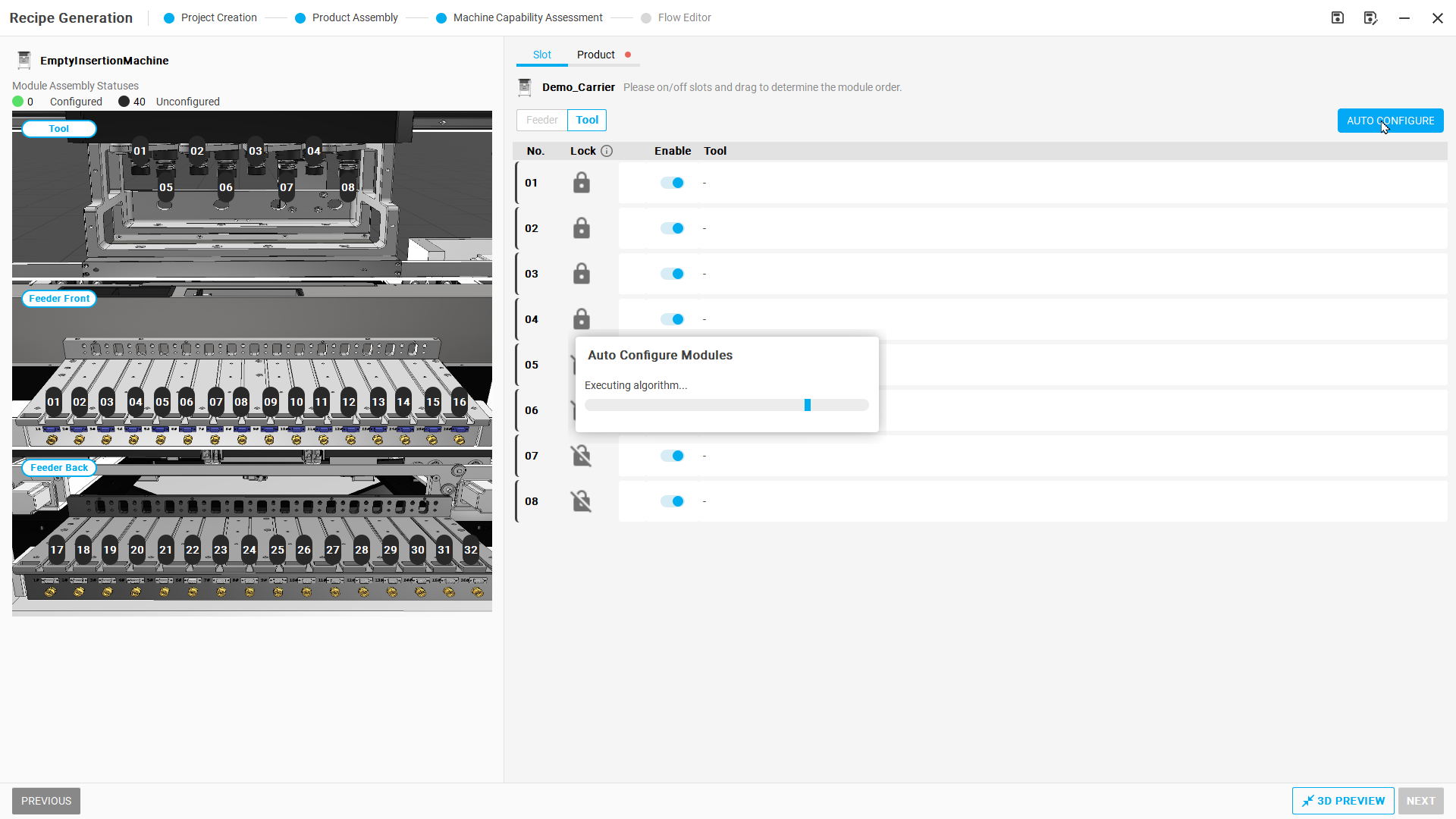
Figure R02-06: Start automatic configuration
Step 07 | Check the Feeder plan
On the Feeder tab in the result window, compare the current configuration with the Auto-Configured proposal. Verify that no Feeder is assigned to 17–32.
Check after the operation: The proposed configuration respects the reserved-empty-slot condition.
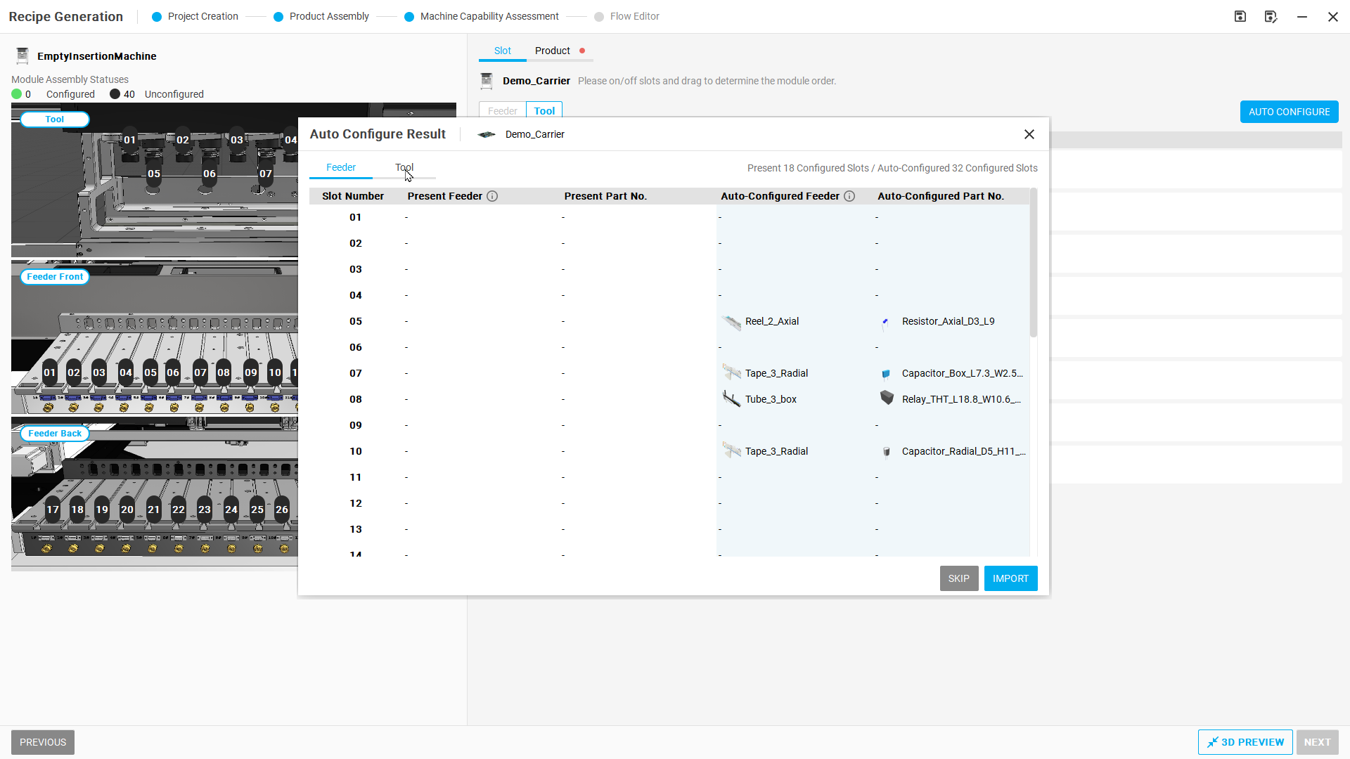
Figure R02-07: Check the Feeder plan
Step 08 | Check the Tool plan
Switch to Tool in the result window and confirm that no Tool is assigned to 1–4.
Check after the operation: The plan uses only permitted tool slots.
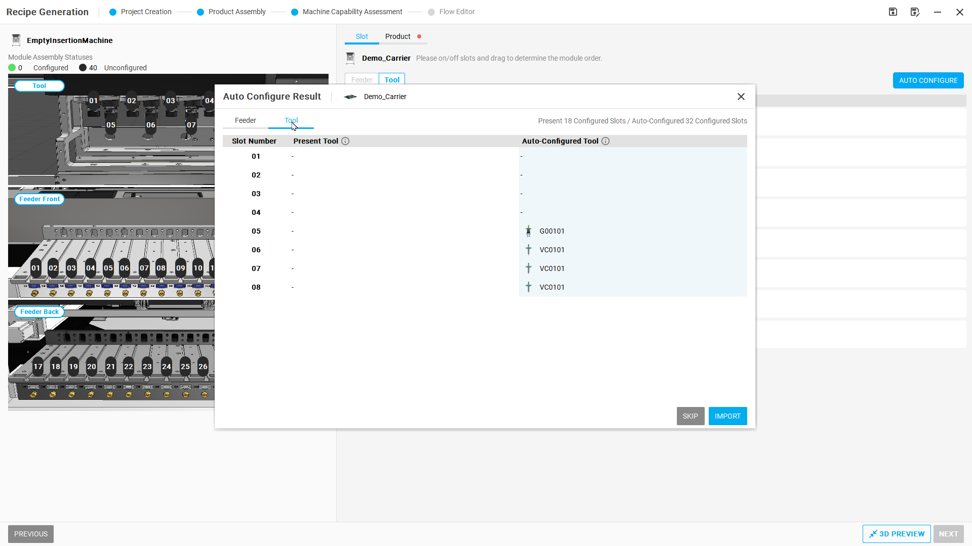
Figure R02-08: Check the Tool plan
Step 09 | Import the configuration
Select IMPORT and read the warning about overwriting the current configuration/process. If adopting this result, select CONTINUE and wait for import to finish.
Check after the operation: The proposed configuration is applied to the machine.
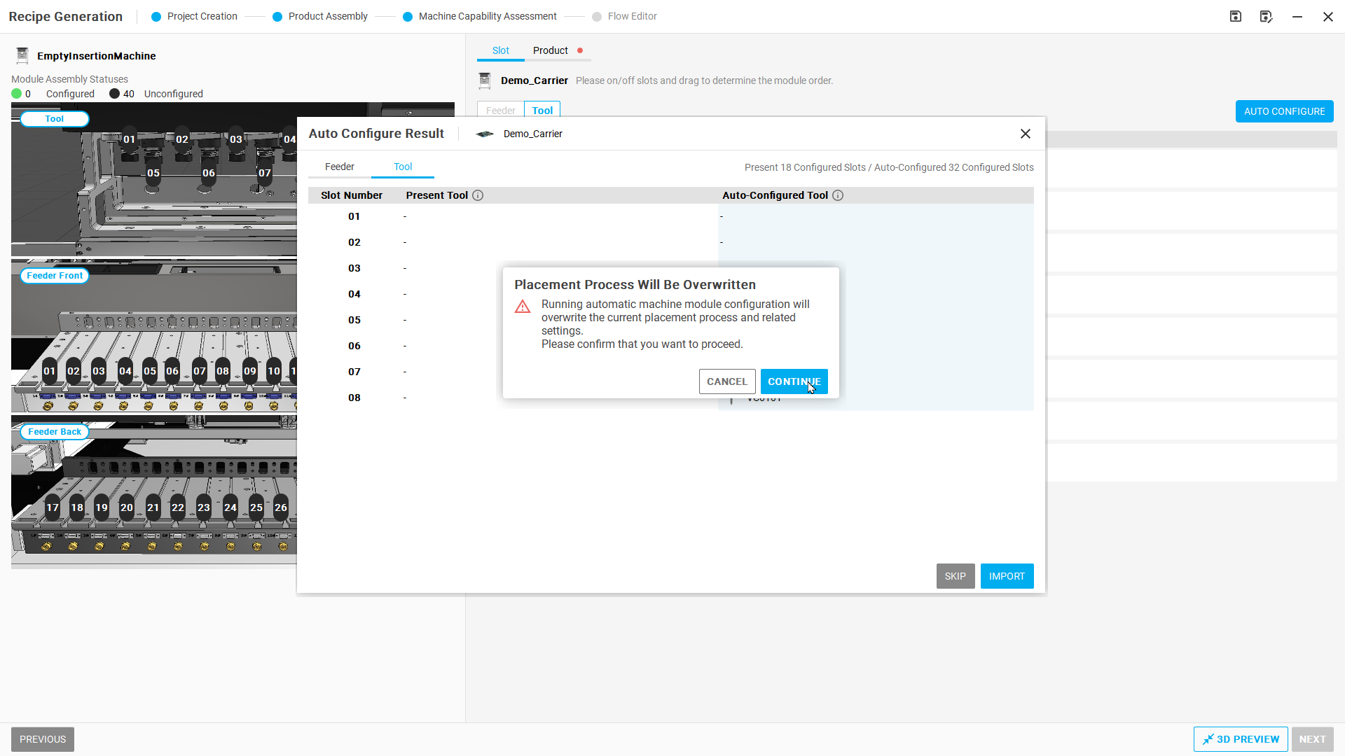
Figure R02-09: Import the configuration
Step 10 | Check applied Feeders
Return to Slot → Feeder. Check installed Feeder slots and part numbers, and confirm 17–32 remain empty.
Check after the operation: The applied configuration respects the constraints.
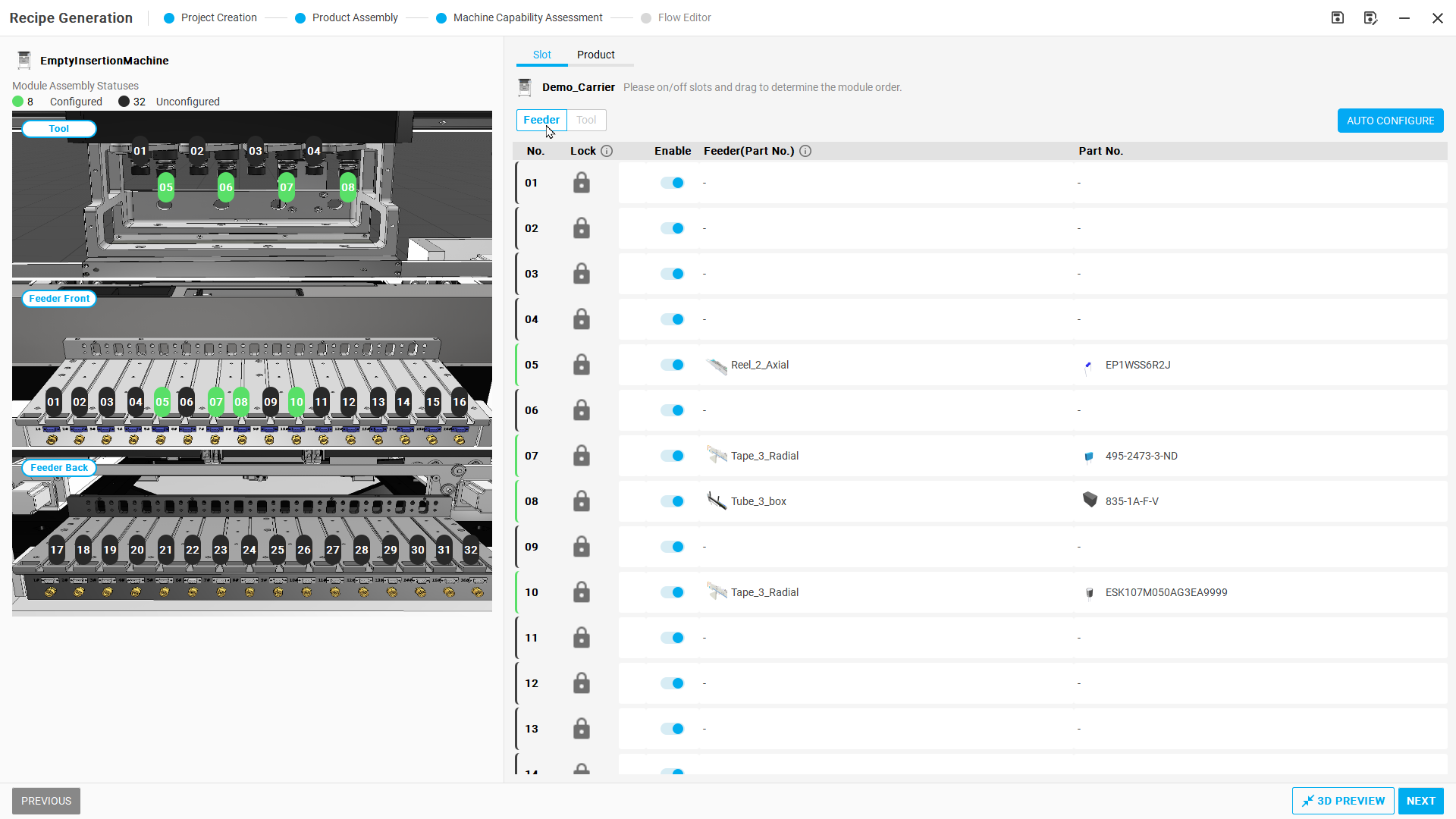
Figure R02-10: Check applied Feeders
Step 11 | Check applied Tools
Switch to Slot → Tool. Confirm tools are installed in permitted slots and 1–4 remain empty.
Check after the operation: The Tool configuration respects the constraints.
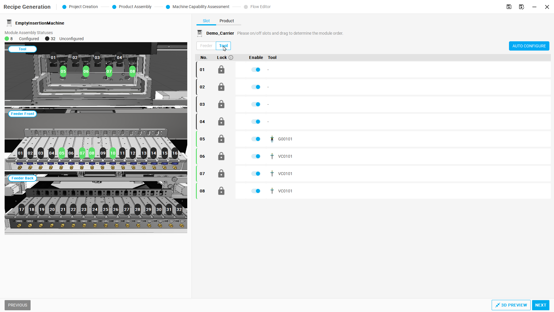
Figure R02-11: Check applied Tools
Step 12 | View the operation flow
Select NEXT to open Flow Editor and inspect the generated pickup and insertion sequence.
Check after the operation: The flow contains processing items.
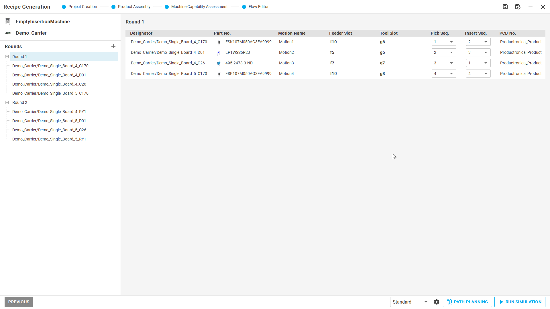
Figure R02-12: View the operation flow
Step 13 | Run simulation
Select RUN SIMULATION. After initialization, select START and wait for this case's simulation to finish.
Check after the operation: Simulation stops in the completed state and Cycle Time can be read.
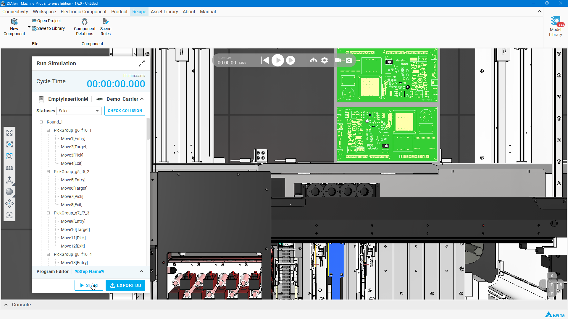
Figure R02-13: Run simulation
Step 14 | Check the result and export command
Record this case's Cycle Time and identify EXPORT DB. The example image shows 12.840 seconds; learners need not reproduce that duration.
Check after the operation: Explain the empty-slot constraints and this simulation result.
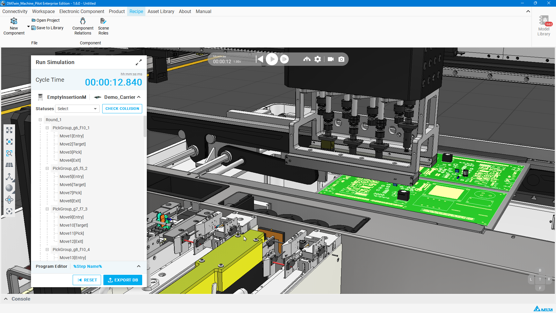
Figure R02-14: Check the result and export command
Completion checks
- [ ] Before planning, Feeder 17–32 and Tool 1–4 are empty and locked.
- [ ] These slots remain empty after import.
- [ ] Simulation is complete and Cycle Time is recorded.
- [ ] Identify EXPORT DB.
Limitations and notes
Lock preserves the current slot configuration: an empty locked slot remains empty, while a populated locked slot retains its accessory. This example restricts empty slots; continue with simulation after importing the configuration.