 DIATwin
P01 | Create, Annotate, and Save a Single Board
Purpose and expected result
Practice creating a single board, importing Gerber, linking the BOM, annotating insertion positions and two fiducials, setting shape, dimensions, and the default locating point, and saving. Use the confirmed Demo_Single_Board as the completed reference. Finish when your product can be found in Recipe.
Before you start
Prepare the standard training Gerber and corresponding component library, and ensure Demo_Single_Board is available in ProductCatalog as a reference. New Single Boards include the UIBU library category by default. Official Gerber data location: C:\Users\Public\DeltaDelectronics\DIATwin\My Model\MachinePilot\gerber\APEX . Follow the specified annotations; recreating the entire reference-board BOM is not required. The TestBoard/C52 example explains the annotation method. Use the part numbers and designators for your own board.
Example values and adjustable items
| Item | Existing method example | Treatment in the final content |
|---|---|---|
| Completed reference | Demo_Single_Board | Confirmed; no repeat confirmation needed |
| Custom name | TestBoard | May be customized |
| Gerber | APEX2024 Layer 1 stencil_2mil.gbr, APEX2024 Layer 1.gbr, APEX2024 Layer1 mask.gbr, APEX2024 Layer1 silk.gbr | Select the specified files from the official APEX folder. |
| Example BOM | C52/495-2473-3-ND | Not presented as the complete reference-board BOM |
| Shape Length / Width / Height | 304.8/165/3mm | Set according to the instructions |
| Fiducials | FID1, FID02 | Names may be customized; two points in total |
Procedure
Step 01 | Create a Board
In Product, select New Board. Enter a custom name in Create Root (TestBoard in the method example), then select OK.
Check after the operation: The tree contains Board, Workpart, BOM, and Mountpoint.
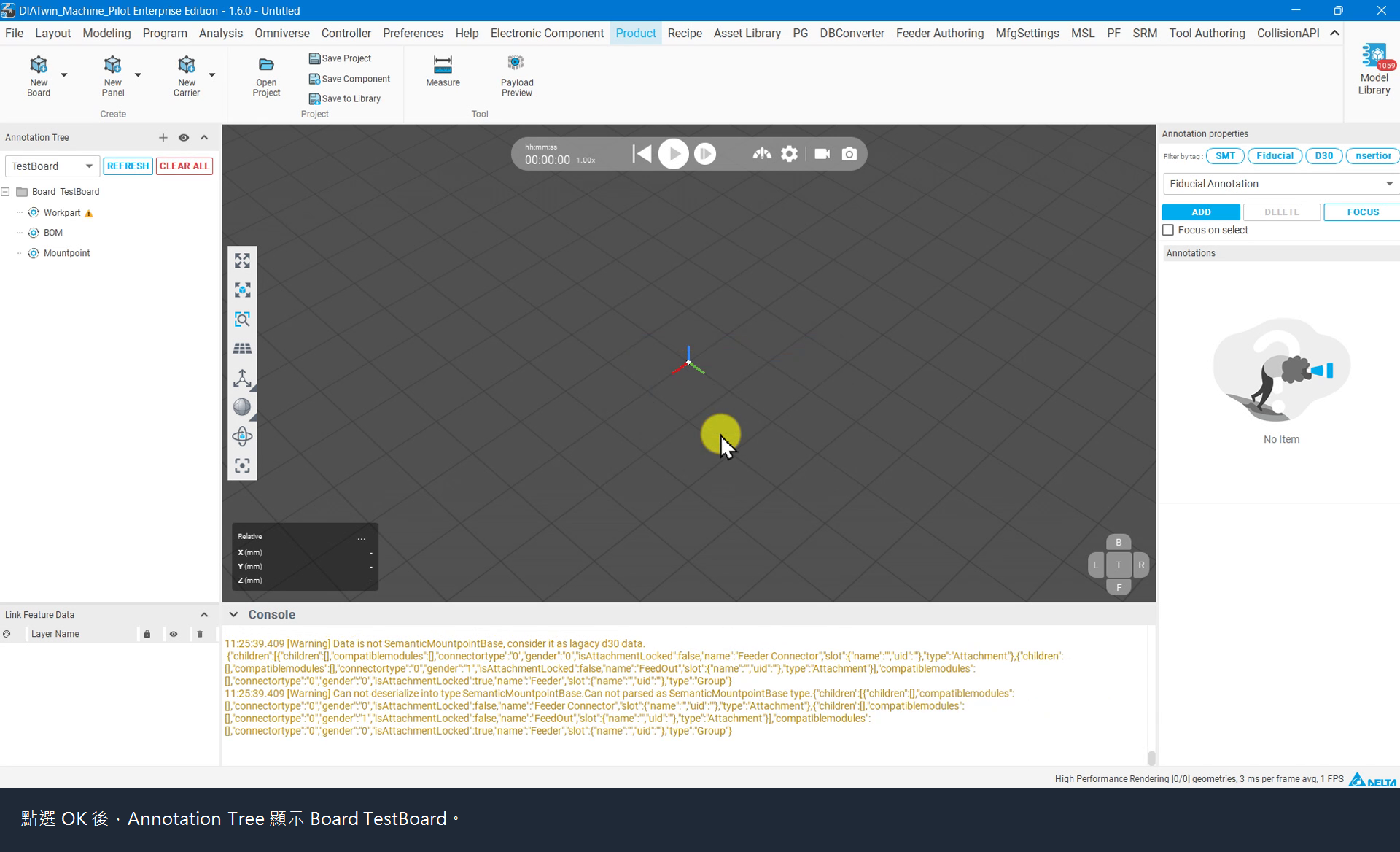
Figure P01-01: Create a Board
Step 02 | Create Gerber and 3D Links
Right-click the Board root → Create Link..., select Top Layer (Gerber), and select OK. Run Create Link... again, select 3D Shape, and select OK.
Check after the operation: Both Link_GerberTop and Link_Shape appear in the tree.
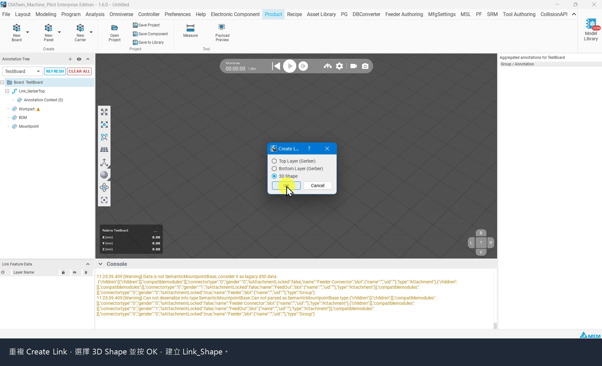
Figure P01-02: Create Gerber and 3D Links
Step 03 | Import Gerber
Right-click Link_GerberTop → Import Gerber Shape.... Hold Ctrl to select the required Gerber files, then select Open. The method example uses the four files listed above.
Check after the operation: Link Feature Data shows the layer names, and Gerber geometry is visible in the 3D viewport.
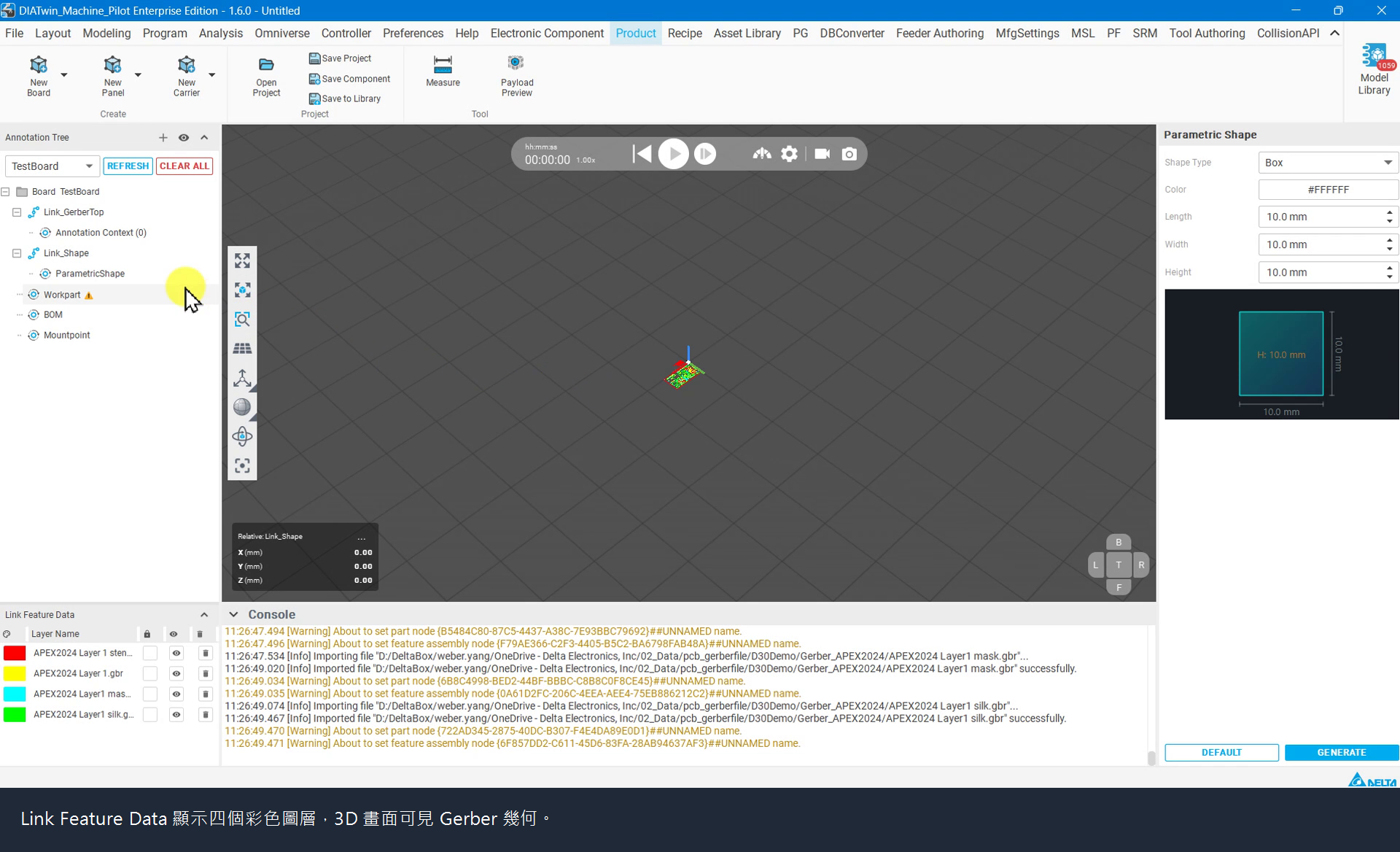
Figure P01-03: Import Gerber
Step 04 | Focus on the board
Right-click the Board root node → Focus Viewport, then adjust zoom with the mouse wheel.
Check after the operation: The board outline and target features can be identified.
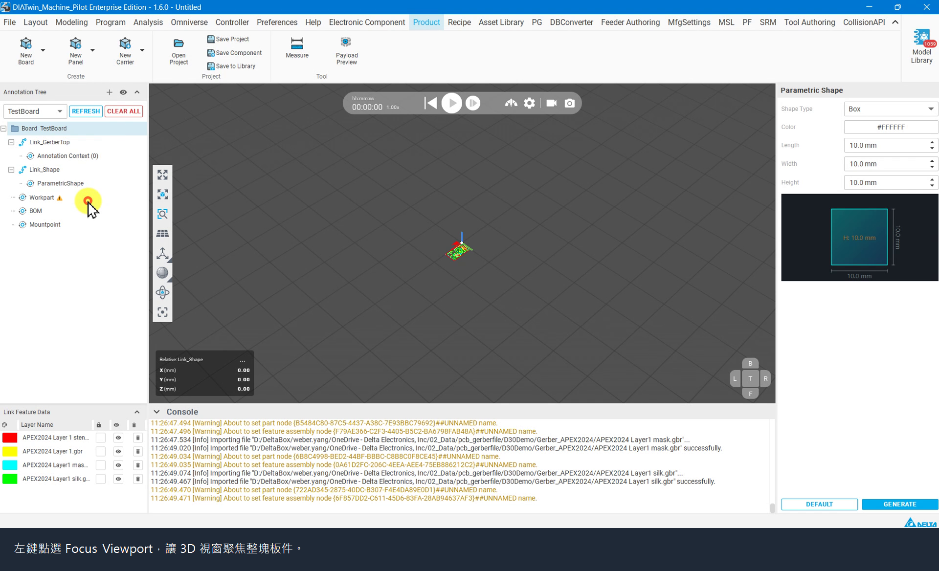
Figure P01-04: Focus on the board
Step 05 | Add a BOM item
Select BOM, then ADD in the right-hand list. Select Part No. in the NEW row to choose a link.
Check after the operation: Component Library Search opens.
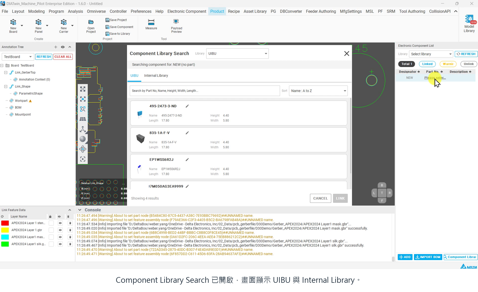
Figure P01-05: Add a BOM item
Step 06 | Link a part number
Select the required part number in UIBU; the example is 495-2473-3-ND. Select LINK, then verify the Part No. link in the BOM.
Check after the operation: The BOM row displays the selected part number.
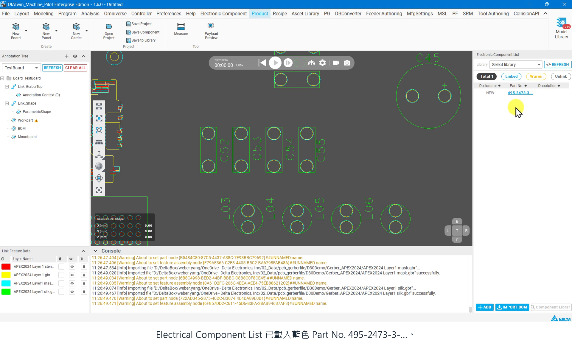
Figure P01-06: Link a part number
Step 07 | Set the Designator
Double-click NEW in Designator, enter the position name (C52 in the example), and press Enter. Annotate the items specified in this task; additional components can be created in further practice using the same method.
Check after the operation: The BOM part number and Designator correspond correctly.
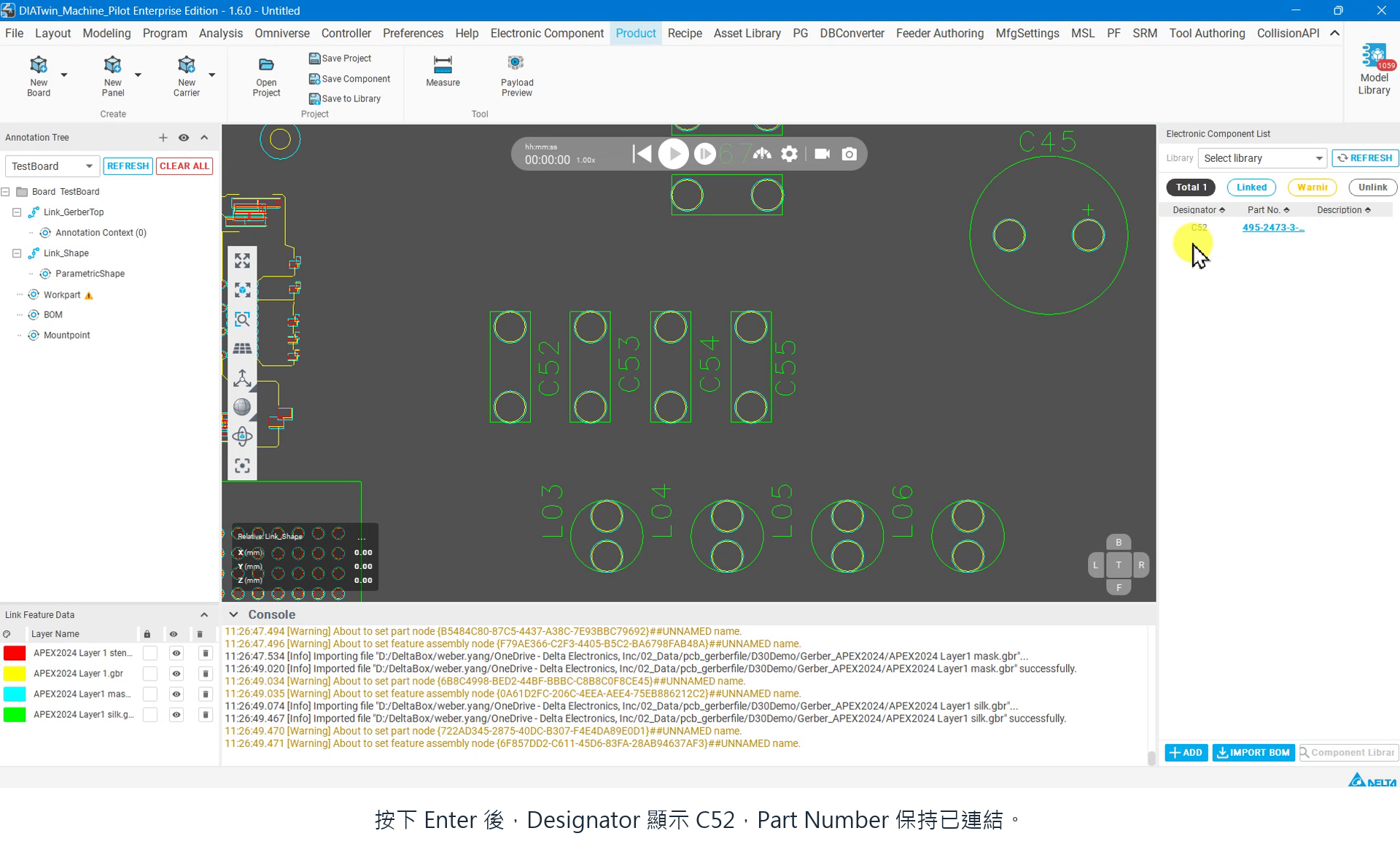
Figure P01-07: Set the Designator
Step 08 | Create an Insertion Annotation
Select Annotation Context. Choose Insertion Annotation on the right and select ADD. Right-click the new item and choose Continuous Edition.
Check after the operation: The insertion annotation editor opens.
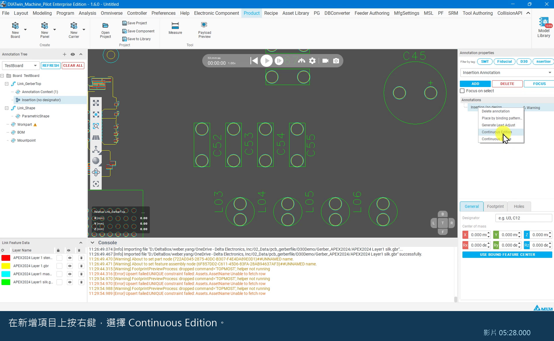
Figure P01-08: Create an Insertion Annotation
Step 09 | Box-select the Footprint
In Continuous Edition, select Footprint. In the 2D view, hold the left mouse button and drag a box around the target features, then release. Check the blue selection outline.
Check after the operation: The selection covers the target component's Footprint.
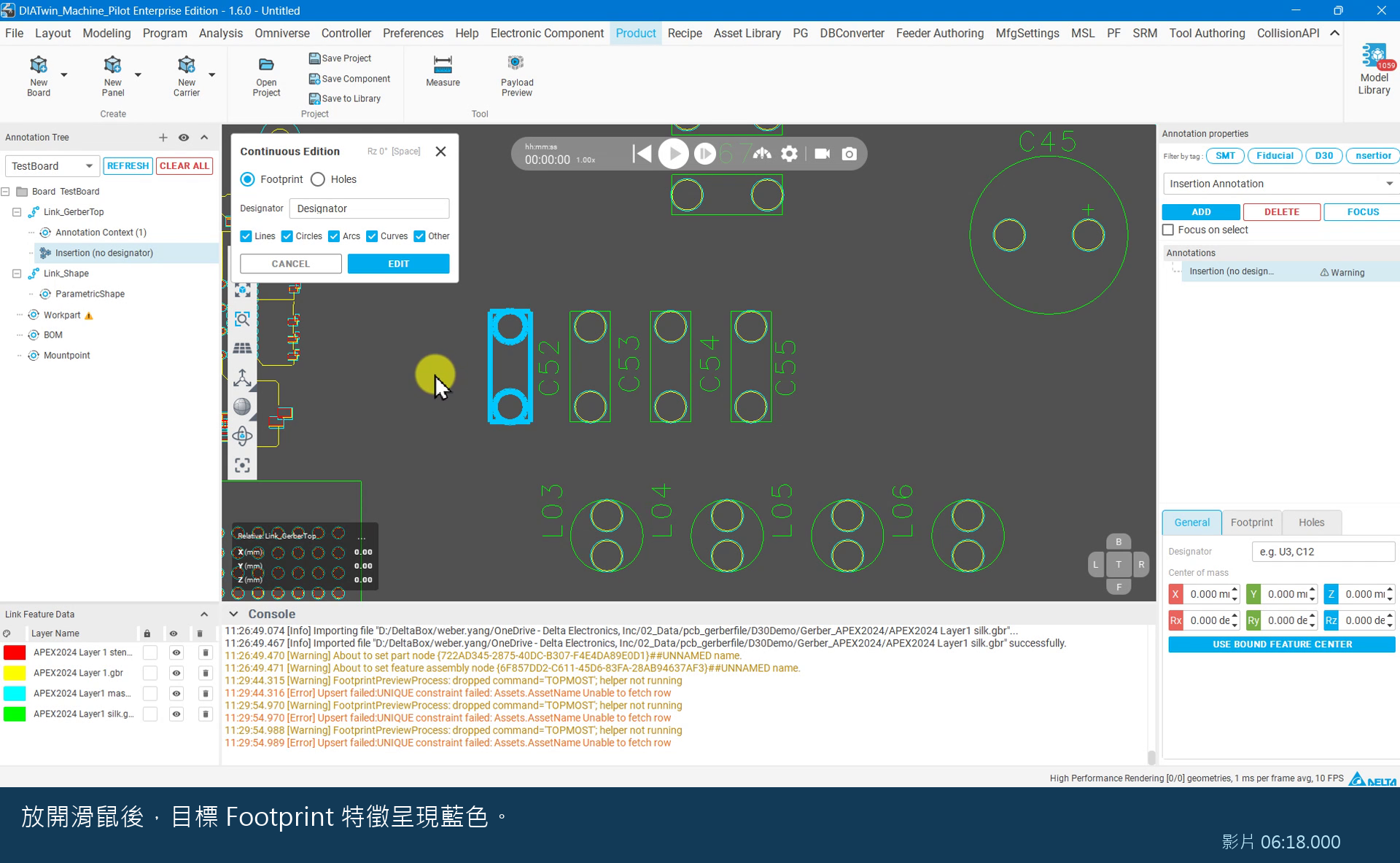
Figure P01-09: Box-select the Footprint
Step 10 | Set the annotation name
Enter the Designator matching the BOM, select EDIT, and verify the name in annotation properties. The final example name is C52; there is no need to deliberately enter C73 first.
Check after the operation: The annotation name matches the BOM.
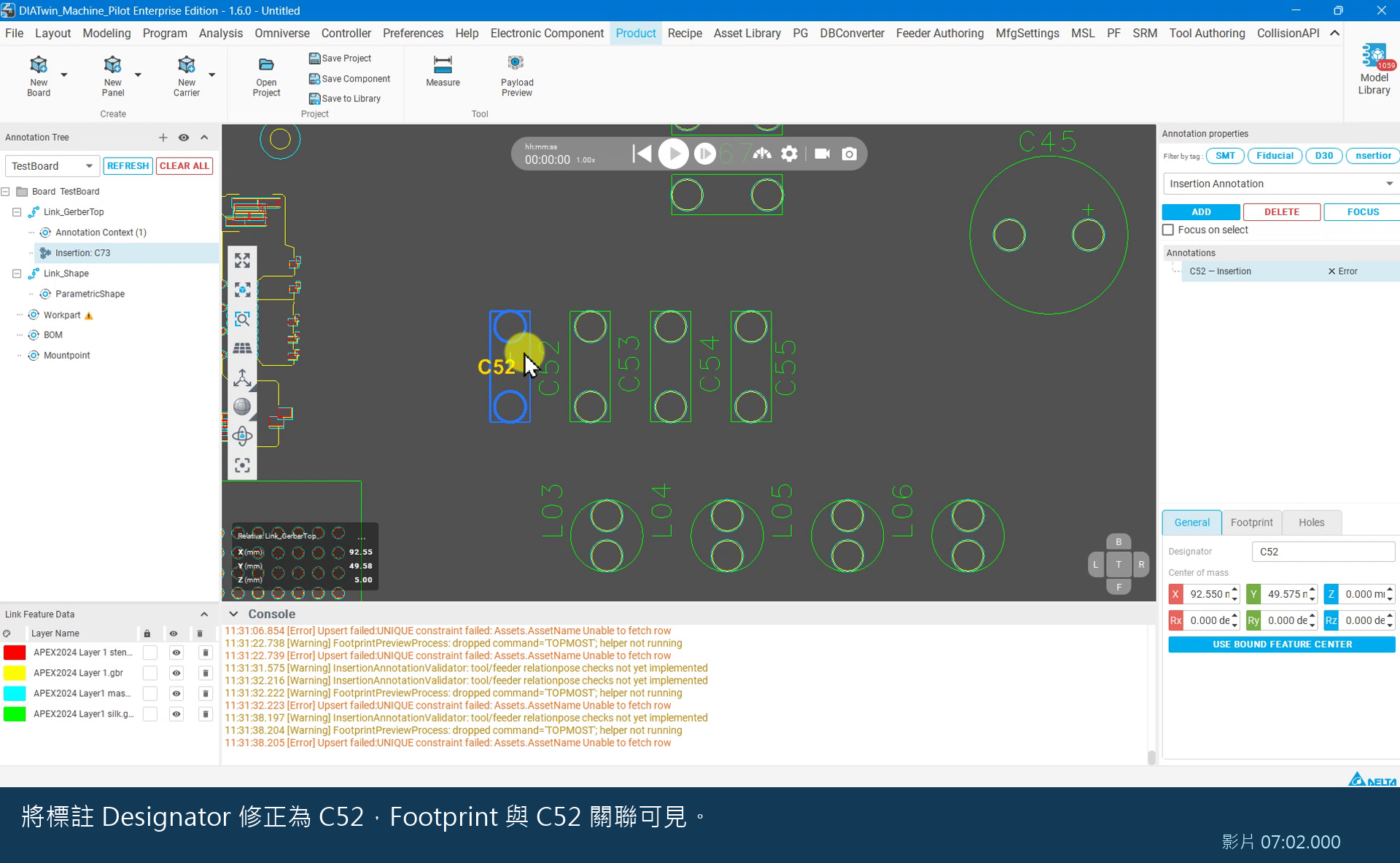
Figure P01-10: Set the annotation name
Step 11 | Run Payload Preview
Select Payload Preview on the toolbar, wait for the model to load, and check component positions against their annotations.
Check after the operation: The 3D component appears at its annotation position.
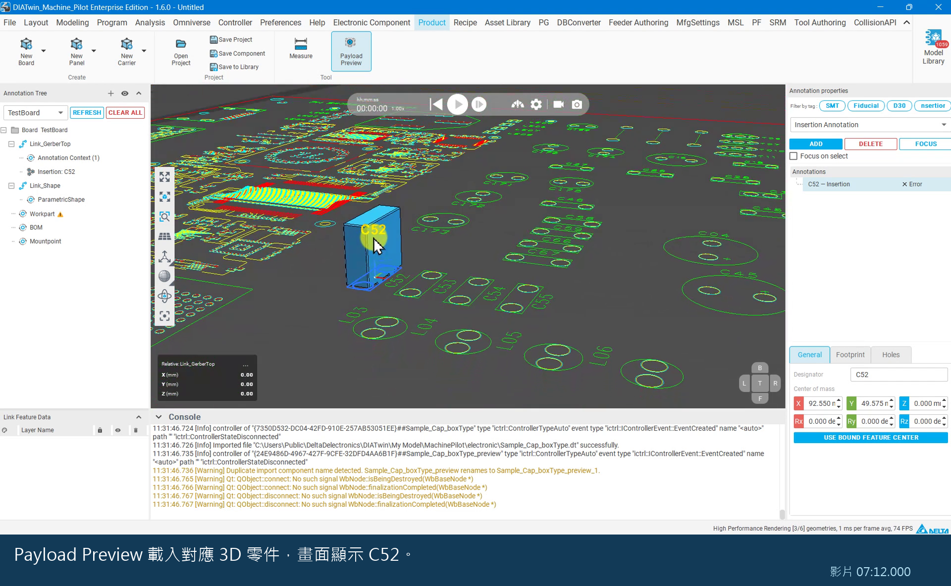
Figure P01-11: Run Payload Preview
Step 12 | Add a fiducial item
Return to Annotation Context. Choose Fiducial Annotation on the right and select ADD. Right-click the new Fiducial item → Continuous Create.
Check after the operation: The fiducial creation window appears.
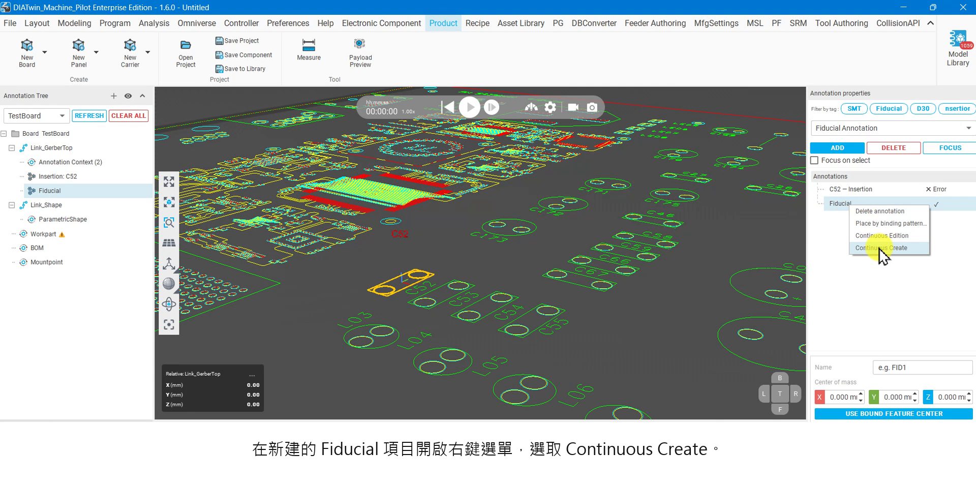
Figure P01-12: Add a fiducial item
Step 13 | Create two fiducials
Enter FID1 in Designator, left-click the first Gerber locating feature, and select CREATE. Enter FID02 for the next item, choose another locating feature, and select CREATE. Select CANCEL to finish.
Check after the operation: The list contains two named Fiducials.
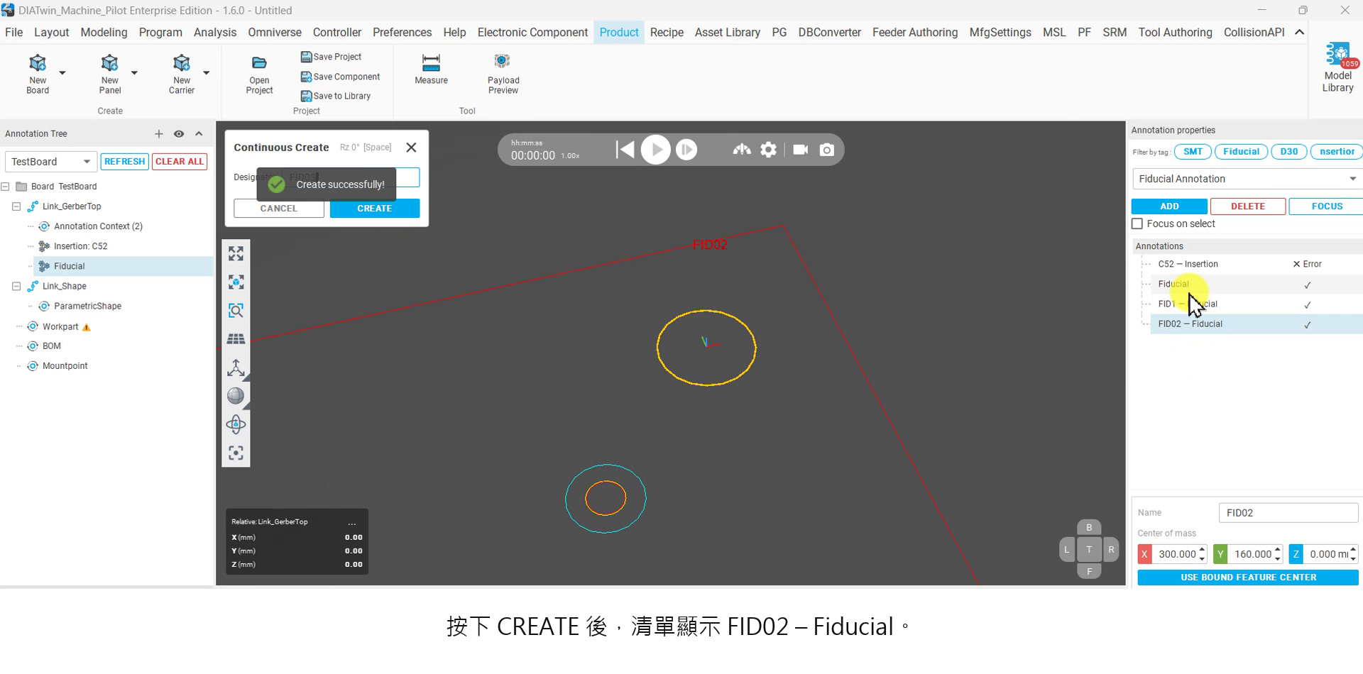
Figure P01-13: Create two fiducials
Step 14 | Set the board shape
Select ParametricShape under Link_Shape and choose the board color. Use Measure on the toolbar to measure two opposite corners of the outline. Enter Length, Width, and Height, then select GENERATE. The example uses 304.8 / 165 / 3 mm.
Check after the operation: The board shape is generated.
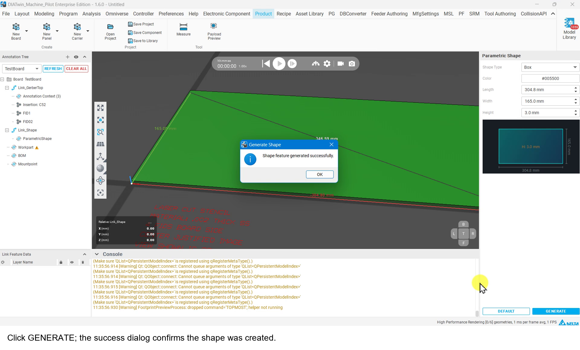
Figure P01-14: Set the board shape
Step 15 | Adjust Gerber height
Exit Measure (if necessary, click once, then press Esc). Right-click GerberTop and choose Move. Enter Z=3.001 and select OK; this corresponds to the example's 3 mm board thickness.
Check after the operation: Gerber appears just above the board surface.
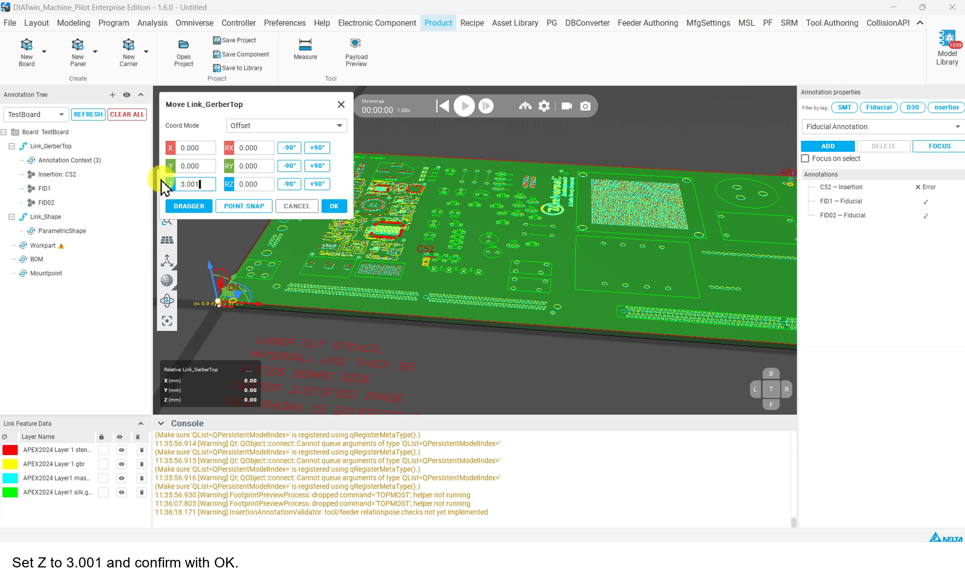
Figure P01-15: Adjust Gerber height
Step 16 | Set Workpart dimensions
Select the Board's Workpart and measure opposite corners to check the overall Width, Length, and Thickness. Final example values are 165 / 304.8 / 3.001 mm; do not treat other initial From Shape readings as final values.
Check after the operation: The dimensions match your board.
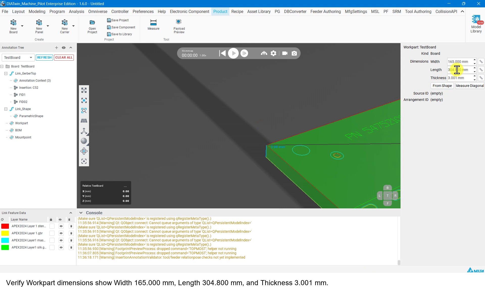
Figure P01-16: Set Workpart dimensions
Step 17 | Create the default Mount Point
Right-click Mountpoint → Create Mount Point, then select Corner Mount Point to inspect the default locating point.
Check after the operation: Corner Mount Point appears in the tree. Advanced Pick / Move / Seat operations are outside this task.
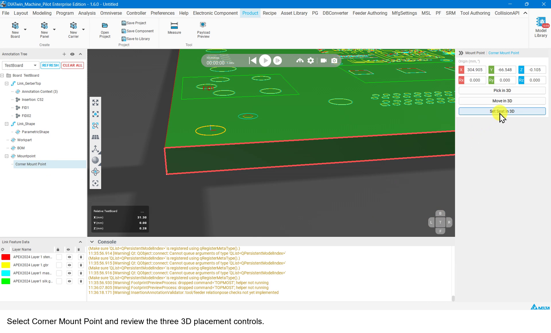
Figure P01-17: Create the default Mount Point
Step 18 | Save your product
Select Save to Library and check Name, Asset version, and Save folder. Choose ProductCatalog under Group membership, select + Add, and confirm it appears in the table. Select Capture from 3D view, check Preview, then select OK.
Check after the operation: A save-success message appears. Check the asset name, then close it.
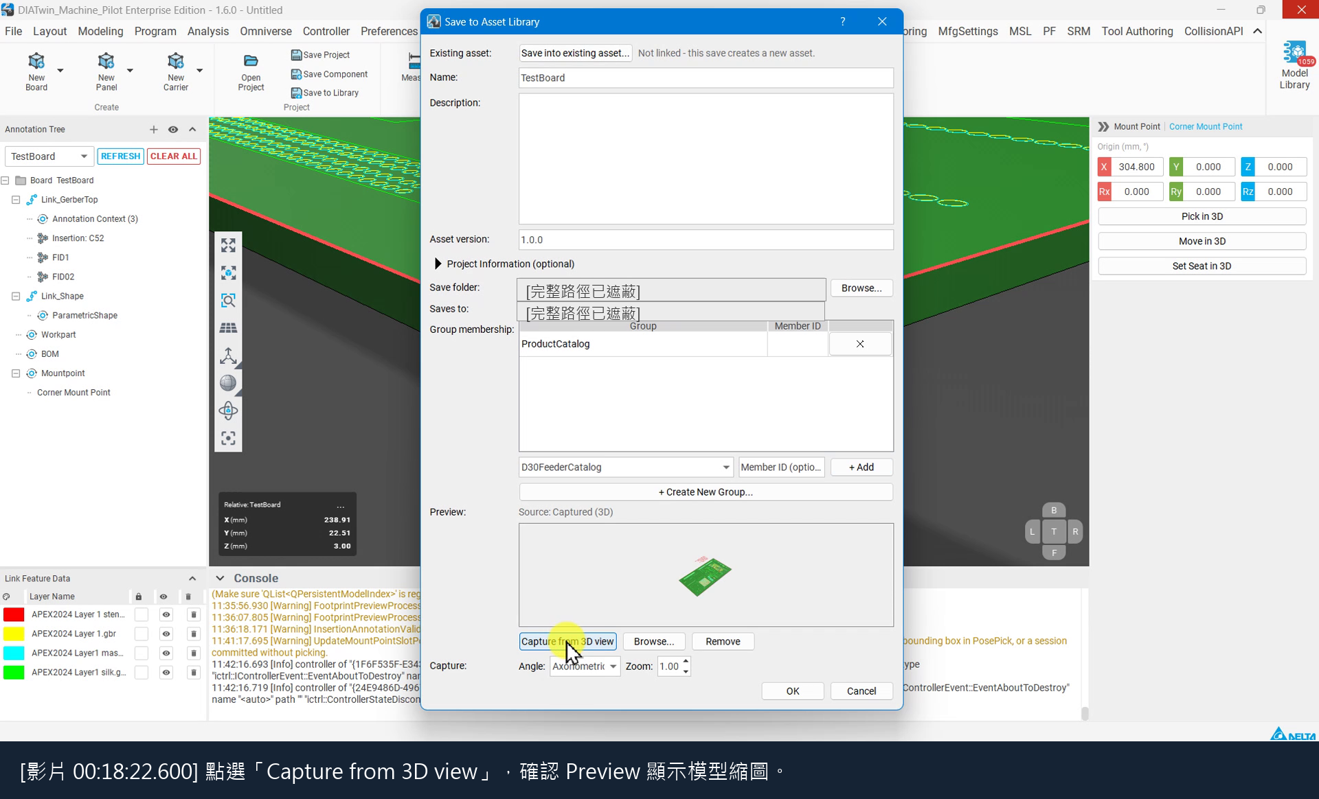
Figure P01-18: Save your product
Step 19 | Find the product in Recipe
Select Recipe, open Create Project in Project Creation, and look for your saved name in the Product list. Use Demo_Single_Board separately as the completed reference.
Check after the operation: Your product can be found and selected in Recipe.
Completion checks
- [ ] Gerber, BOM, and required annotations have been created for the single board.
- [ ] BOM and Insertion Designators match, and components are visible in Payload Preview.
- [ ] Two named fiducials, board dimensions, and a default Mount Point are present.
- [ ] The saved product can be found in Recipe; its name need not match the example.
Limitations and notes
Compare the completed product with Demo_Single_Board and check designators and part numbers against your BOM. Resolve any reported errors before continuing. Hole settings, Reload Product, and advanced positioning are covered separately.