 DIATwin
R01 | Assign Resources and Process Board by Board
Purpose and expected result
Manually assign feeders, tools, and slots for each part number. Use Panelized to apply one board's plan to the other boards, then plan paths and simulate.
Before you start
Use EmptyInsertionMachine and the standard Demo_Panel. The library must contain the accessories listed below. This is the four-board Demo_Panel; P02's two-board result is not required.
Example values and adjustable items
| Part number | Feeder / slots | Tool / slots |
|---|---|---|
| 495-2473-3-ND | Tape_3_Radial/08 | VC0101/02, 06 |
| 835-1A-F-V | Tube_3_box/12 | VC0101/04, 08 |
| EP1WSS6R2J | Reel_2_Axial/10 | G00101/03, 07 |
| ESK107M050AG3EA9999 | Tape_3_Radial/06 | VC0101/01, 05 |
These are reproducible examples shown in the images. You may change the configuration, but must explain the mapping between your part numbers, accessories, and slots. Example conveyor width: 350 mm.
Procedure
Step 01 | Create a Recipe
Select Recipe and open Create Project in Project Creation. Select the empty machine and Demo_Panel, then select NEXT.
Check after the operation: Product Assembly opens.
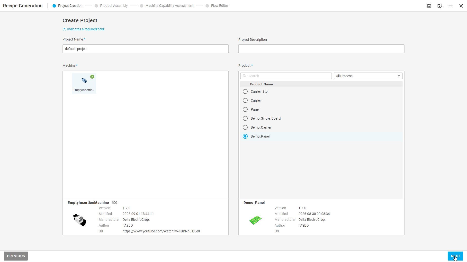
Figure R01-01: Create a Recipe
Step 02 | Set conveyor and mounting conditions
Select L2R in Select Position. Check and confirm the orientation and default Attachment Point in sequence. In Adjust Conveyor Width, enter 350 mm, select CONFIRM, then NEXT.
Check after the operation: After confirming all four assembly steps, proceed to Machine Capability Assessment.
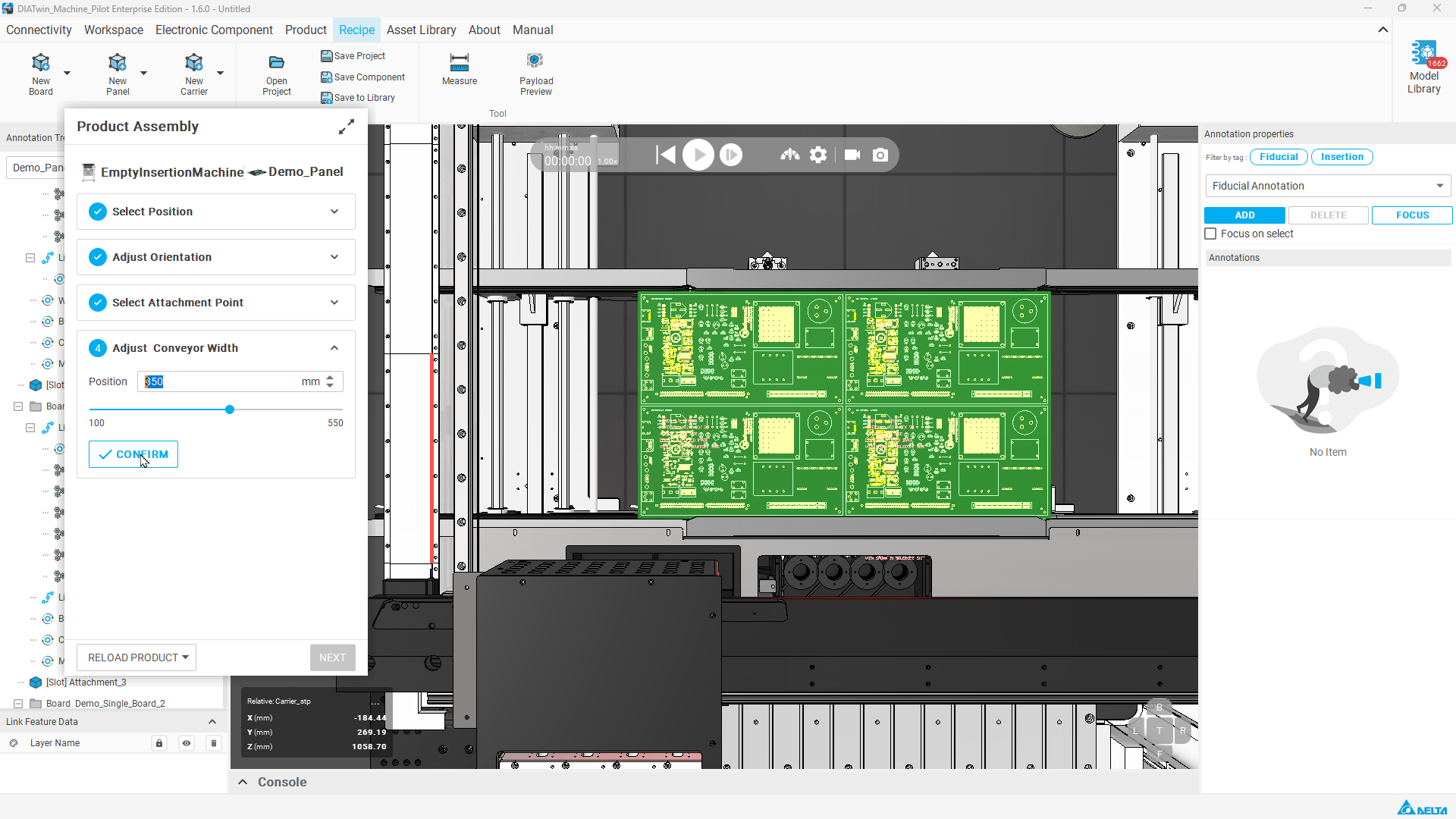
Figure R01-02: Set conveyor and mounting conditions
Step 03 | Open the product configuration list
In Machine Capability Assessment, switch to Product → Feeder and inspect the part numbers and unconfigured items.
Check after the operation: Each part number can be checked against Feeder and Feeder Slot.
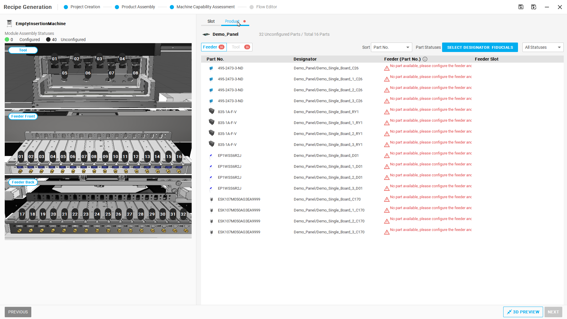
Figure R01-03: Open the product configuration list
Step 04 | Manually assign feeders
In Product → Feeder, left-click the target part number's Feeder field to open Configure Module. In Select Module, choose Tape_3_Radial and select NEXT. In Select Slot, select 08 on the machine diagram, verify Selected Feeder slot=8, and select DONE. Wait for Installation Completed and confirm that every row with the same part number shows Tape_3_Radial / 08. Repeat for other part numbers using the table above.
Check after the operation: The four part numbers show the listed Feeders; configured positions are green.
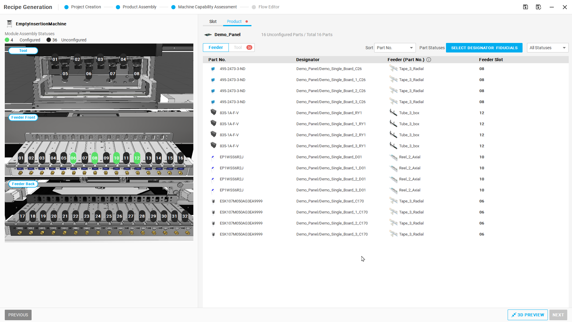
Figure R01-04: Manually assign feeders
Additional operation-detail images (2026-09-17)
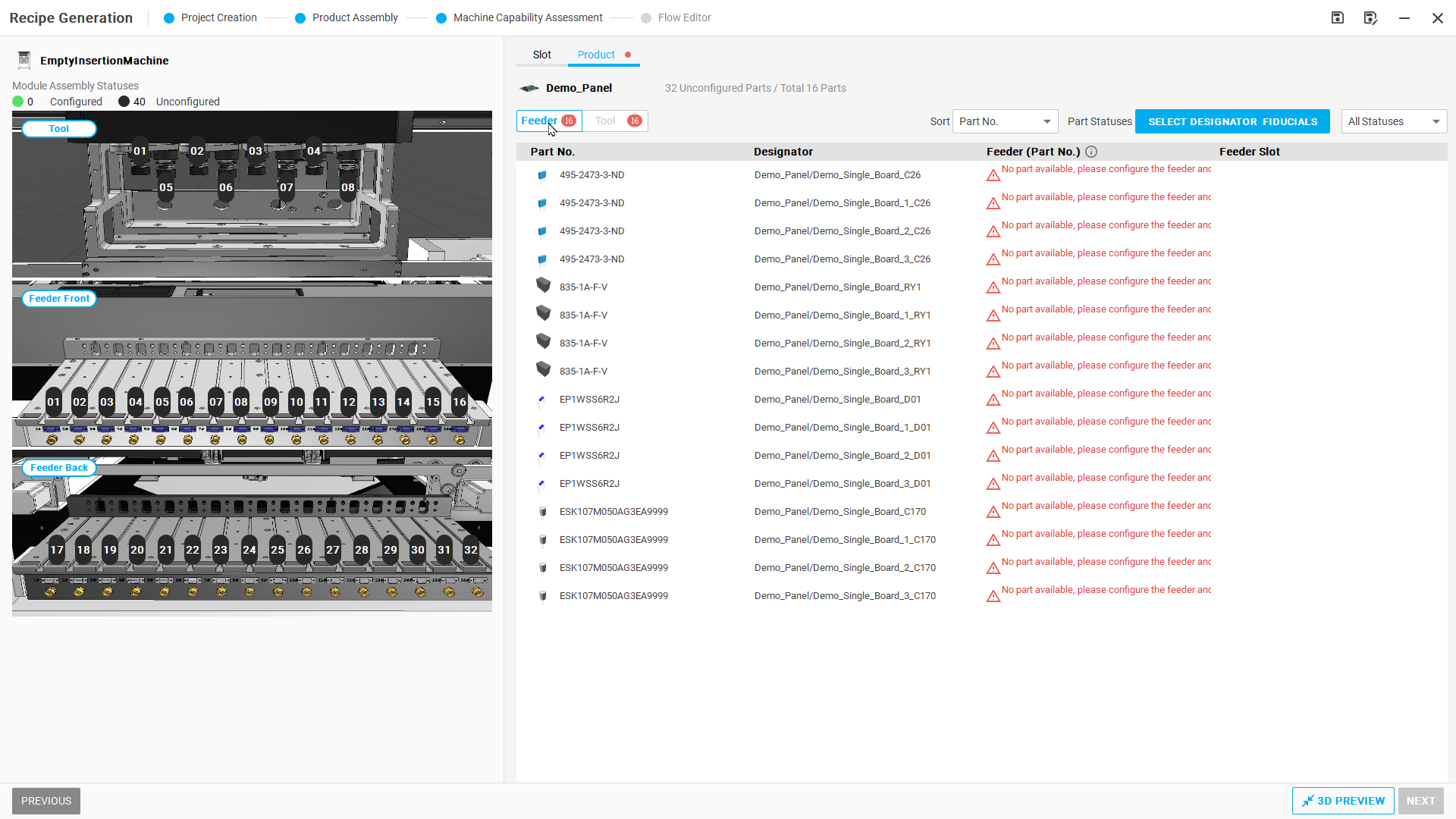
Unconfigured list in Product → Feeder.
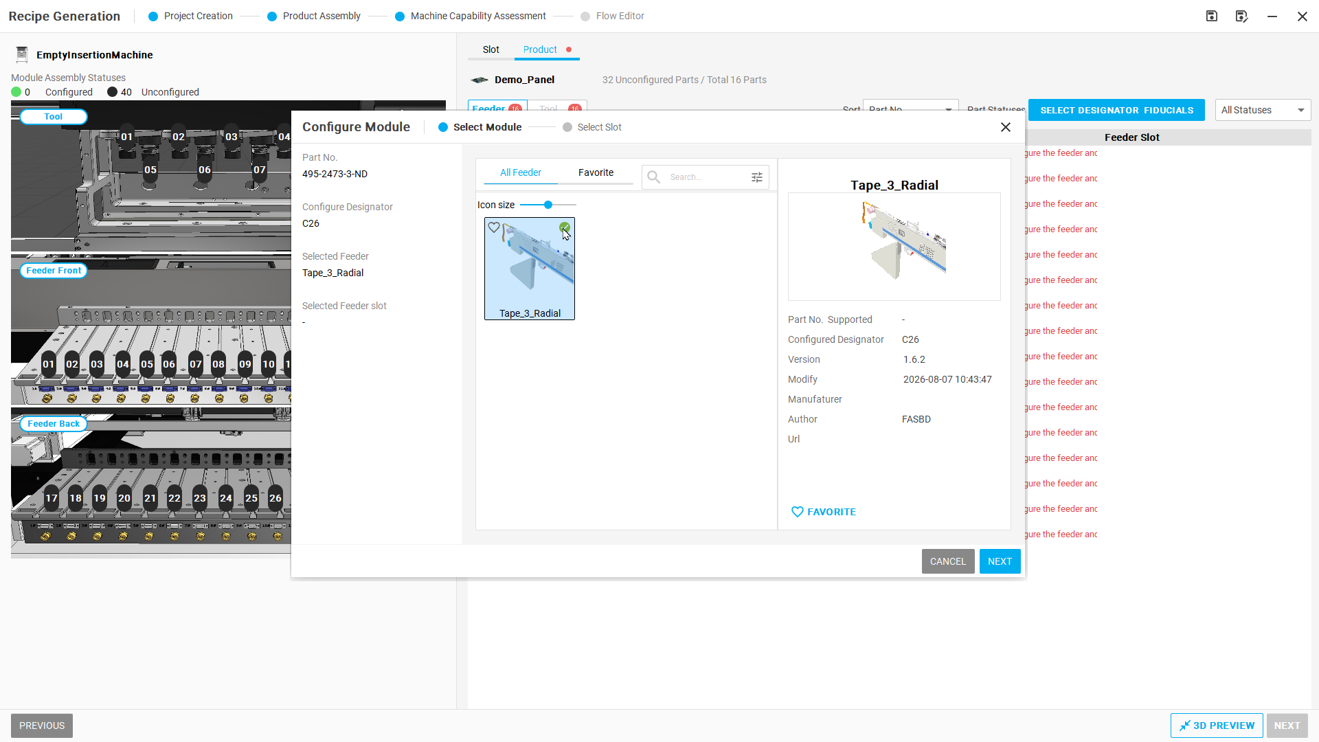
Select Tape_3_Radial, then NEXT.
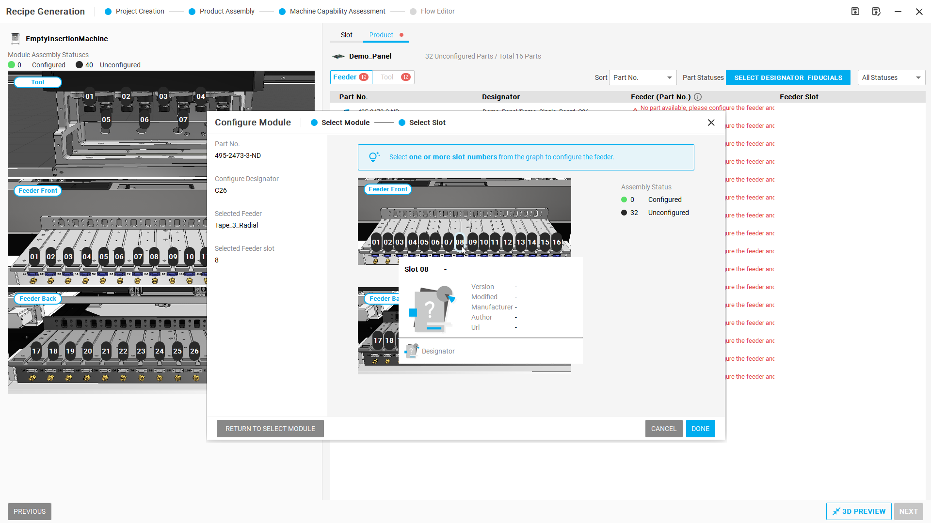
Select Feeder 08, then DONE.
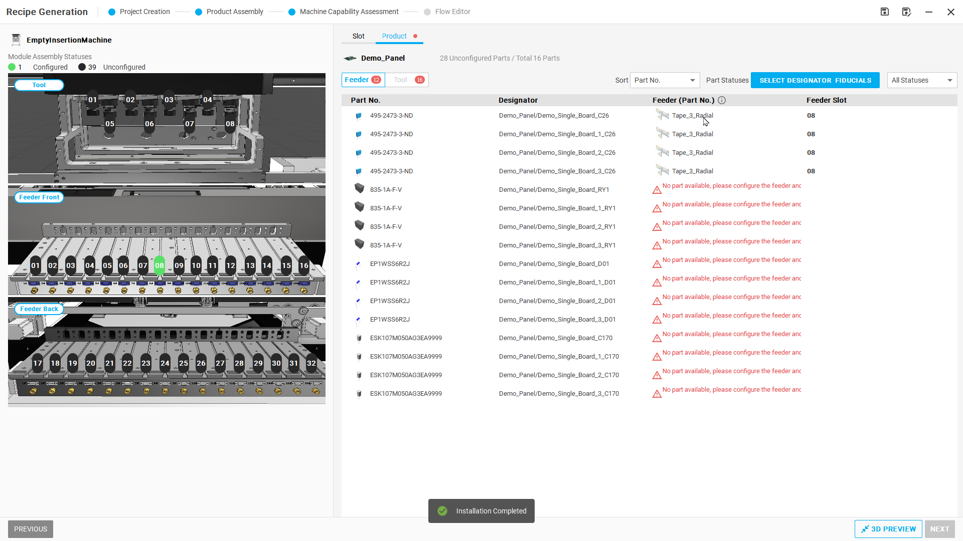
Installation Completed; all four rows for the part number show 08.
Step 05 | Manually assign tools
Switch to Product → Tool. Left-click the target part number's Tool field to open Configure Module. For 495-2473-3-ND, select VC0101 in Select Module, then NEXT.
In Select Slot, choose slots for your practice configuration:
- Complete configuration example: left-click 02 and then 06, without Ctrl. Confirm both slots are selected, then select DONE.
- Single-slot detail images below: select only 06, confirm Selected Tool slot=6, then select DONE. This demonstrates the method; you do not need to complete a single-slot configuration before repeating it with two slots.
Wait for Installation Completed, then check that all rows for the part number match your tool and slot choices. Repeat for the other part numbers and check the entire list. The illustrated single-slot example uses 06. For the two-slot configuration, select both 02 and 06.
Check after the operation: All four part numbers show their assigned tools and chosen slots. When following the complete table example, each part number uses the two listed slots.
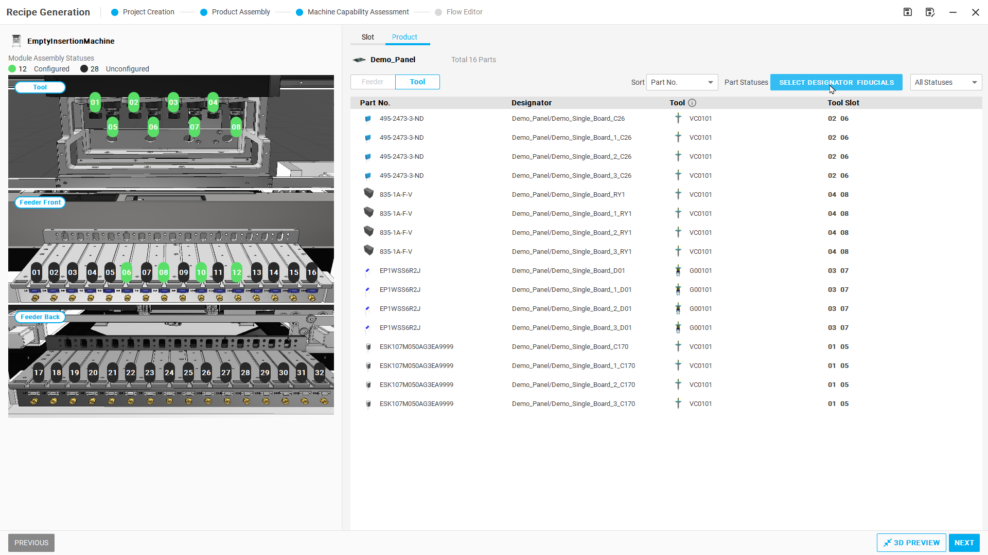
Figure R01-05: Manually assign tools
Additional operation-detail images (2026-09-17)
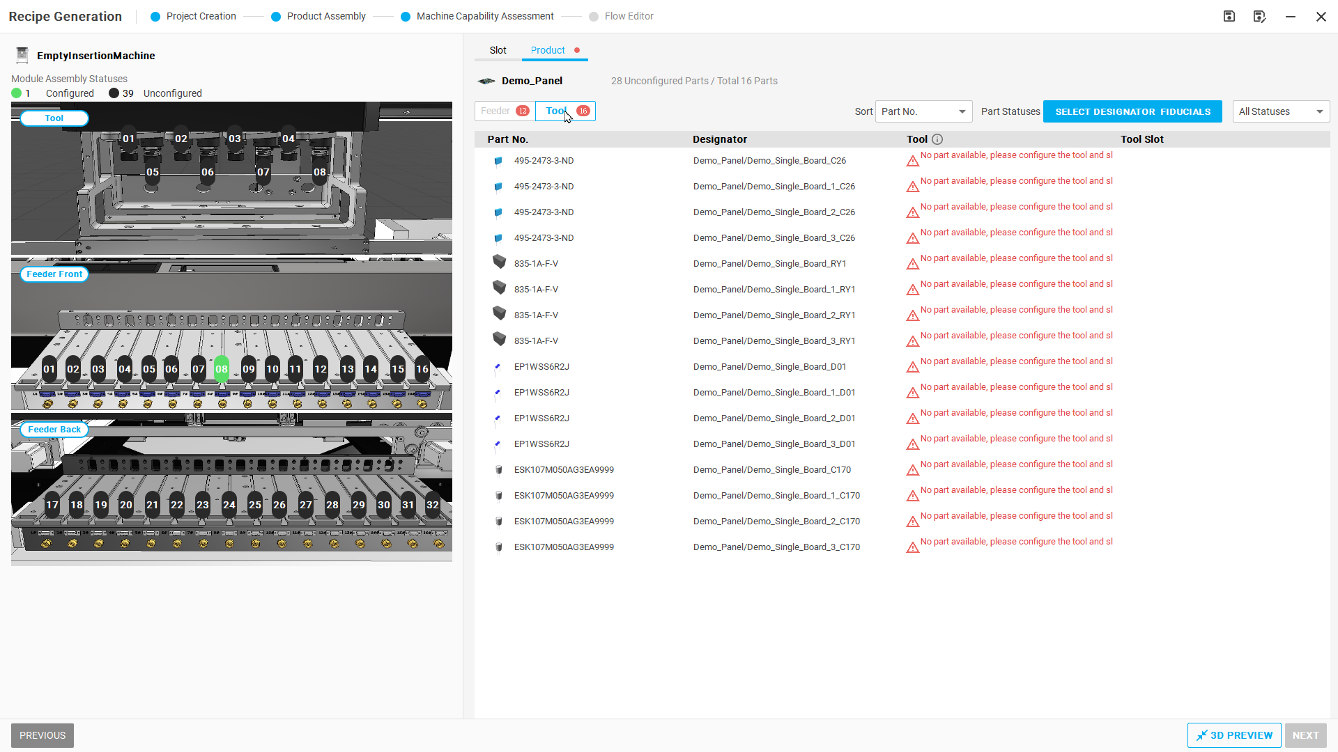
Unconfigured list in Product → Tool.
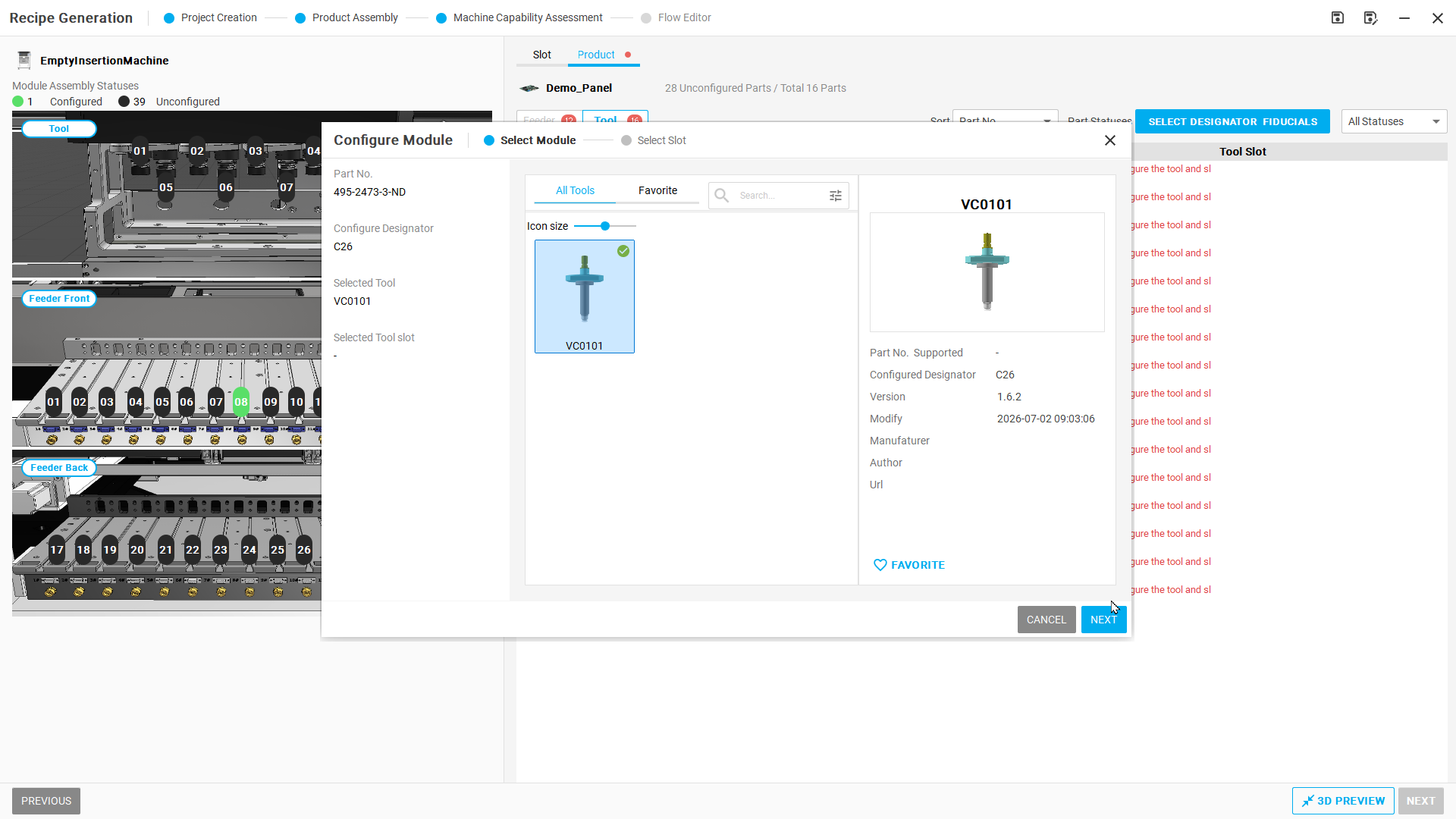
Select VC0101, then NEXT.
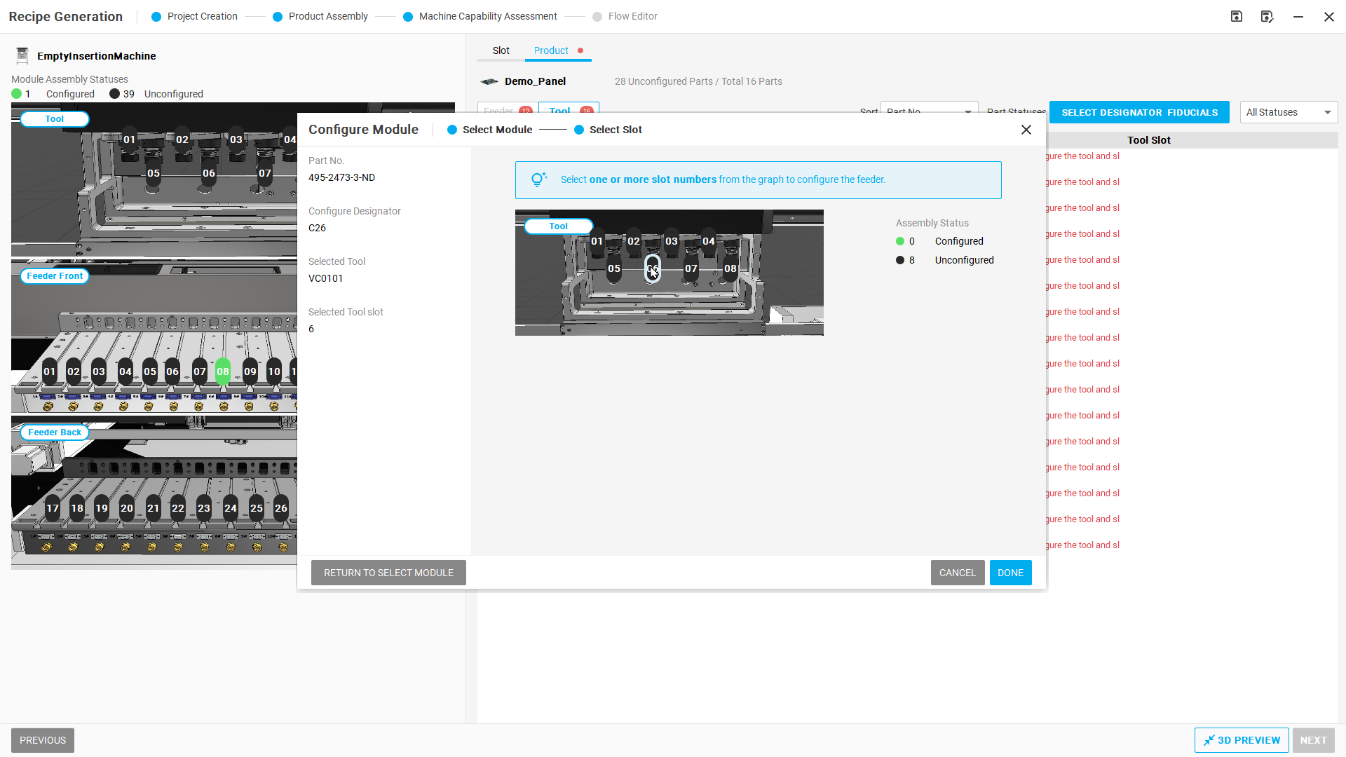
Select Tool 06, then DONE.
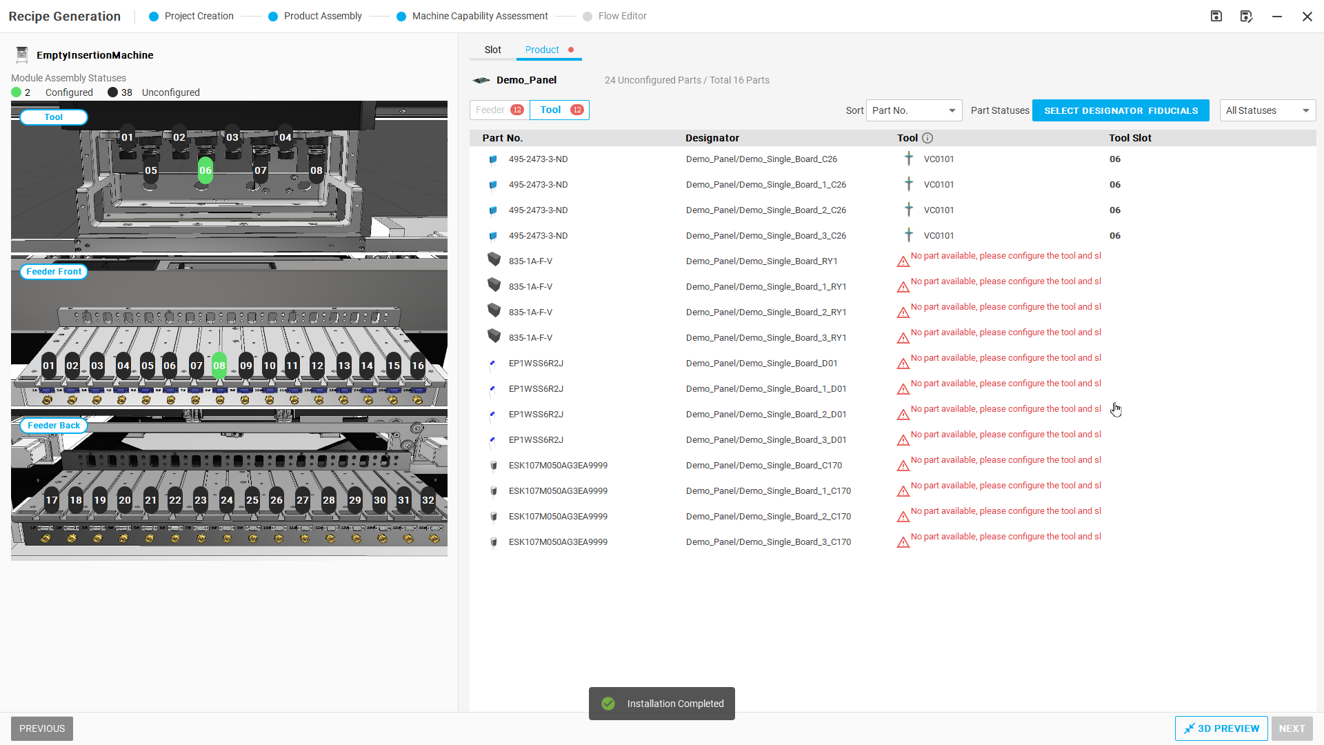
Installation Completed; all four rows for the part number show 06.
Step 06 | Open processing-scope settings
Select SELECT DESIGNATOR FIDUCIALS at the upper right.
Check after the operation: Open Select Designators & Fiducials to view Flattened panel and Panelized.
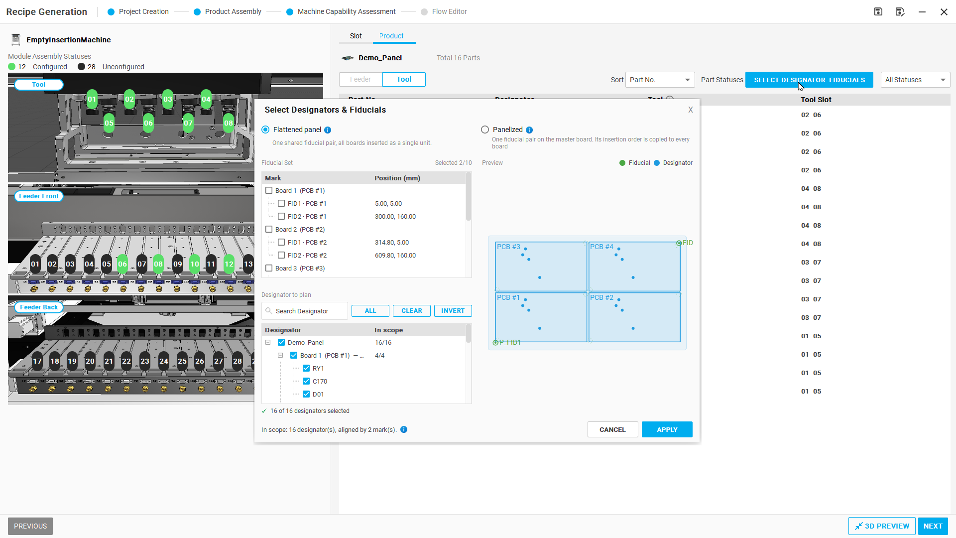
Figure R01-06: Open processing-scope settings
Step 07 | Select Panelized
Select Panelized. Retain the required Designators and the selected P_FID1 and P_FID2. Select APPLY, then NEXT.
Check after the operation: The mode plans one board and applies it to the other boards.
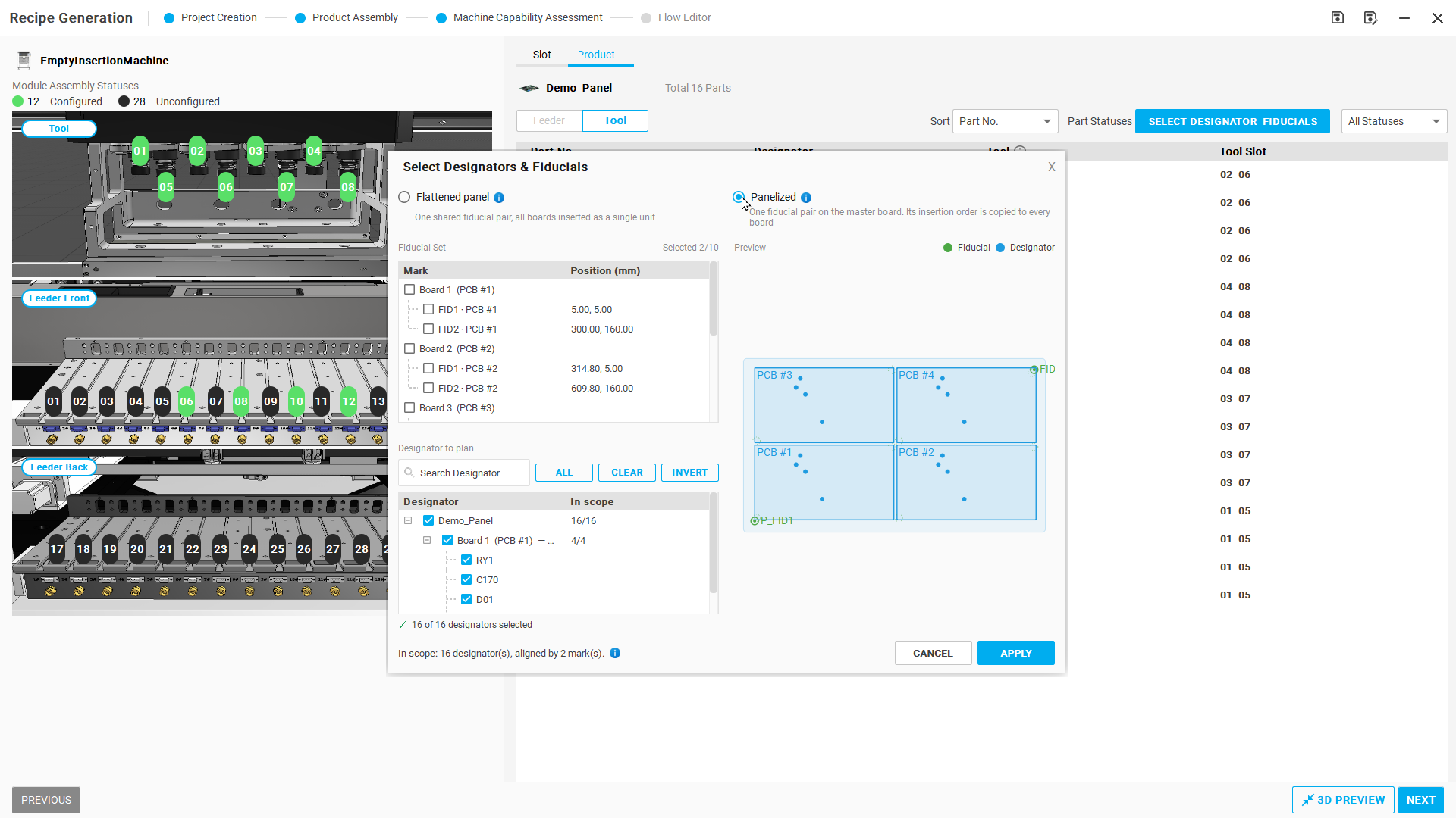
Figure R01-07: Select Panelized
Step 08 | Plan the pick-and-place sequence
In Flow Editor, select PATH PLANNING and wait for the algorithm to finish.
Check after the operation: The screen lists the generated pickup and insertion sequence.
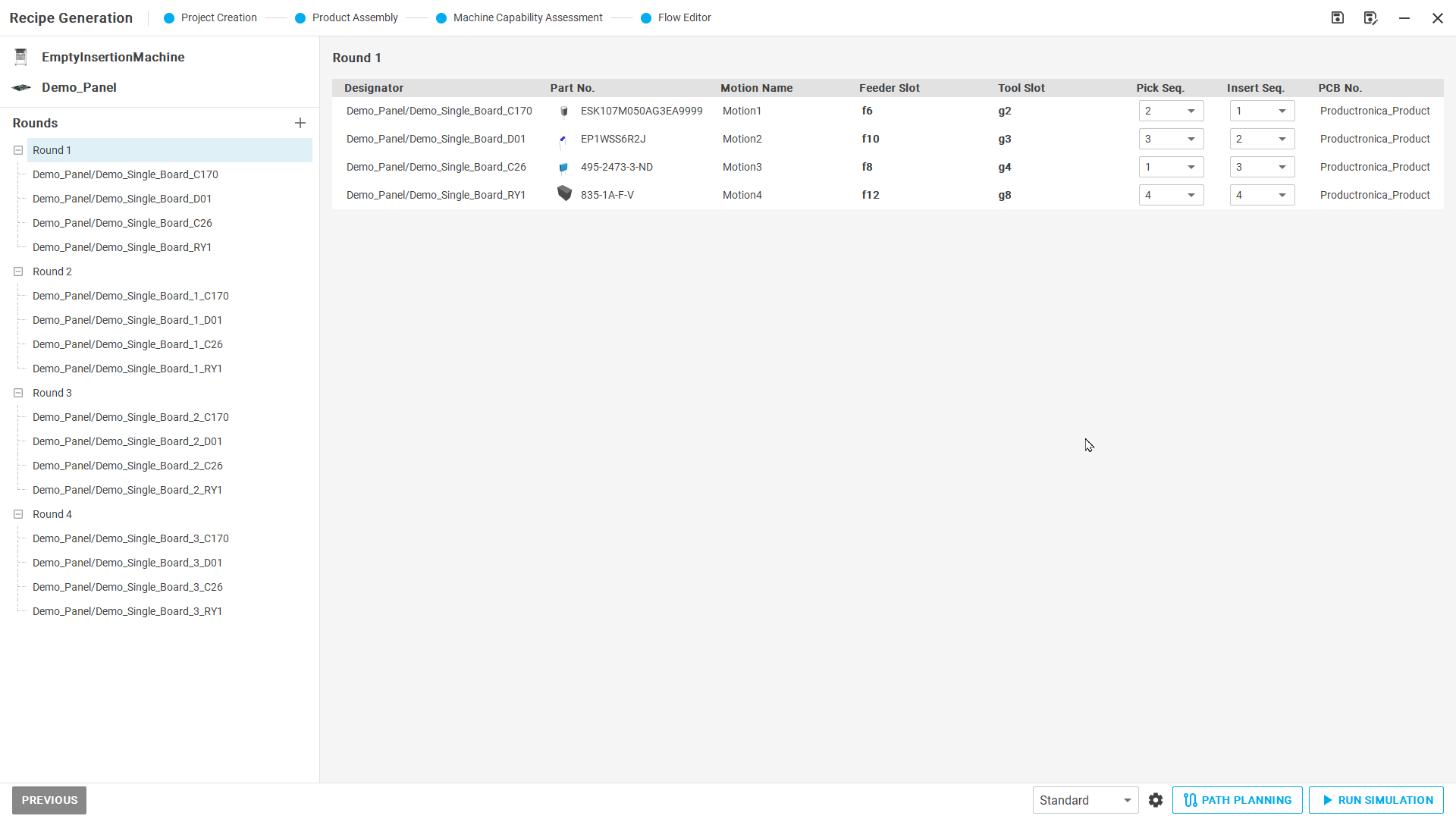
Figure R01-08: Plan the pick-and-place sequence
Step 09 | Open simulation
Check the operation flow, select RUN SIMULATION, and wait for initialization.
Check after the operation: The Run Simulation panel shows START.
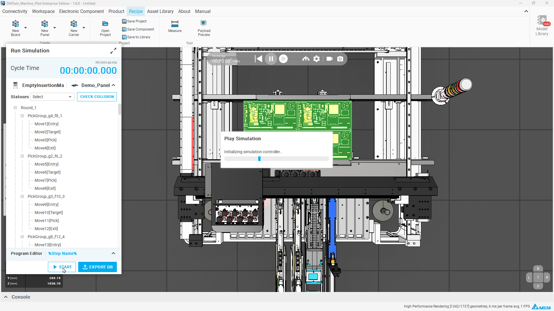
Figure R01-09: Open simulation
Step 10 | Run and check the completed result
Select START, observe processing board by board, and wait for the entire simulation to finish before reading Cycle Time. Identify EXPORT DB; actual export is not required in this task.
Check after the operation: The example result is 31.800 seconds. Record your own result; the same duration is not required.
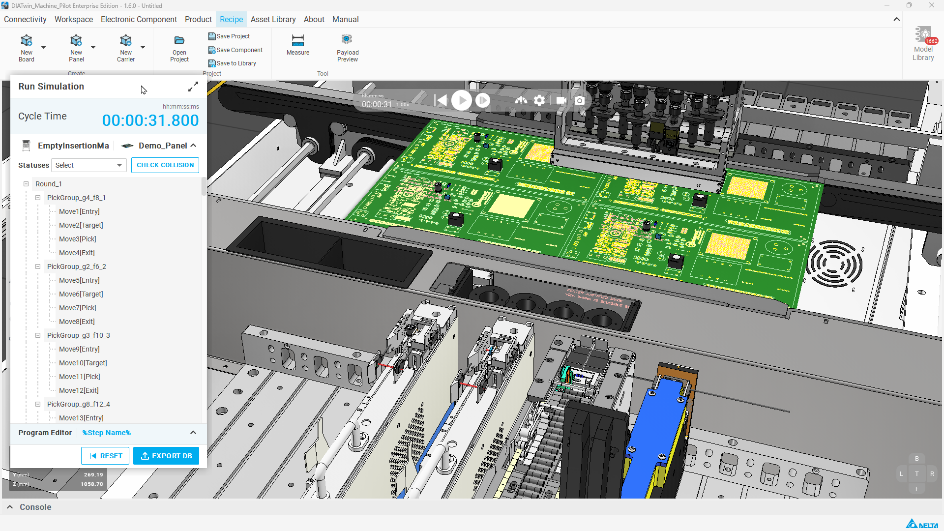
Figure R01-10: Run and check the completed result
Completion checks
- [ ] Identify the Feeder, Tool, and slots used for each part number.
- [ ] Panelized mode is applied.
- [ ] Paths are generated, simulation is complete, and Cycle Time can be read.
- [ ] Know where EXPORT DB is located.
Limitations and notes
This example assigns accessories and slots without additionally locking empty slots. The count of unconfigured empty slots does not mean that all components are unassigned. Check collision results and physical machine conditions after simulation.